|
Dismantling and assembling transmission (R 25/R
28/R 30)
|
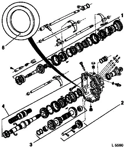
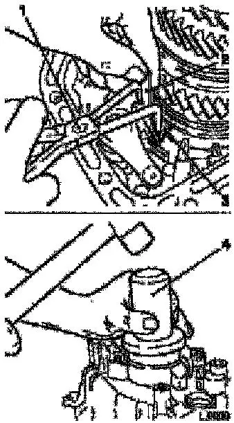
Illustration – Assemblies
| 1. |
Drive shaft assembly |
| 2. |
Reverse idler gear shaft assembly |
| 3. |
Auxiliary shaft gear cluster assembly |
| 4. |
Main shaft assembly |
| 5. |
Supporting disk (additional for all R 30 and for R
25 / R 28 transmissions as of MY 2001) |
|
|
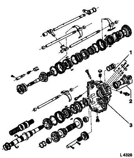
| 1. |
Lock ball assembly |
| 2. |
Drive shaft flange assembly |
| 3. |
Transmission extension assembly |
|
|
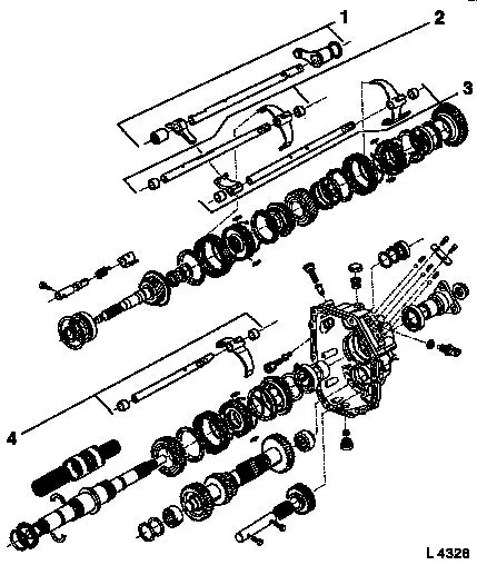
| 1. |
Shift lever shaft assembly |
| 2. |
3rd/4th gear shift rod assembly |
| 3. |
1st/2nd gear shift rod assembly |
| 4. |
5th/reverse gear shift rod assembly |
|
|
 Remove Remove
|
Removing transmission - see operation "Removing and installing
manual transmission (vehicles with 4-cylinder petrol engine)",
"Removing and installing manual transmission (X 20 DTH, Y 22 DTH)",
"Removing and installing manual transmission (25 DT, X 25 DT)",
"Removing and installing manual transmission (Y 25 DT) or "Removing
and installing manual transmission (vehicles with V6 engine)".
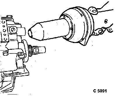
 Install
KM-622 to transmission nose piece, transmission to KM-113-2.
|
|
|
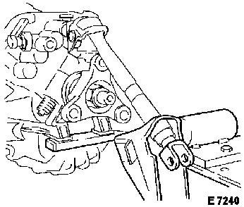
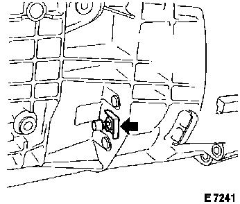
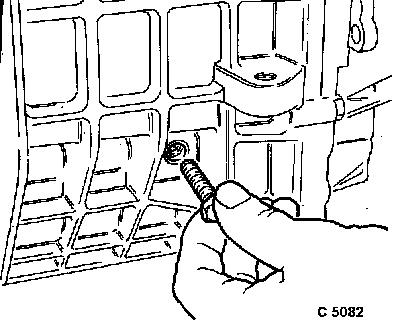
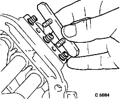
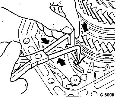
Remove
Remove retaining plate (arrow) for vent line –
commercially available pliers.
|
|
|
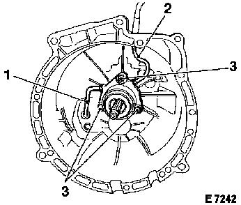
Unscrew pressure line (2) from central release.
Loosen vent line (1) at central release.
Release central release from transmission, 3 bolts (3).
Remove entire central release with vent line (1). Unscrew vent
line from central release.
Pull pressure line (2) out of transmission housing with rubber
sleeve.
|
|
|
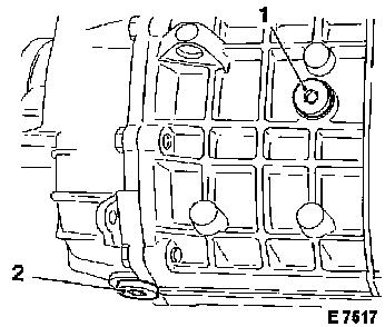
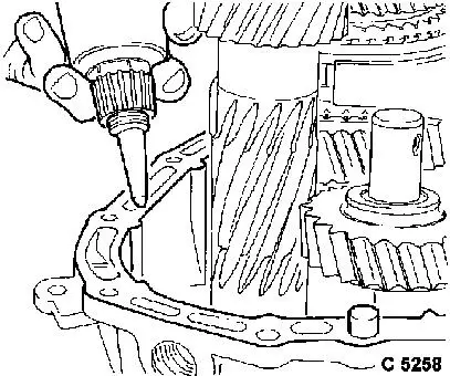
Fluid filler plug (1) from right transmission side, fluid drain
plug (2) from transmission nose piece.
Drain transmission fluid.
|
|
|
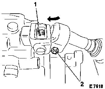
Connecting piece with shift rod from shift lever shaft.
Fold folding cover forwards (arrow), detach retaining clip (1),
drive out pin with suitable drift and hammer.
Caution
Outer shift rod (2) remains attached.
|
|
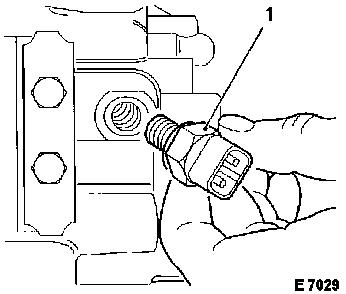
Remove
|
Unbolt reversing lamp switch (1) from transmission. Note spacer
ring.
|
|
|
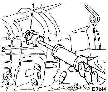
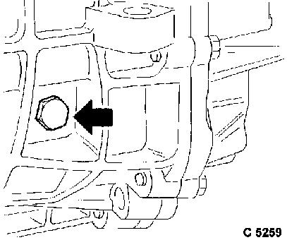
Knock 1 closure plug (1) for locking bolt out of transmission
housing, KM-630-1 (1) and KM-328-B (2) (right transmission
side).
|
|
|
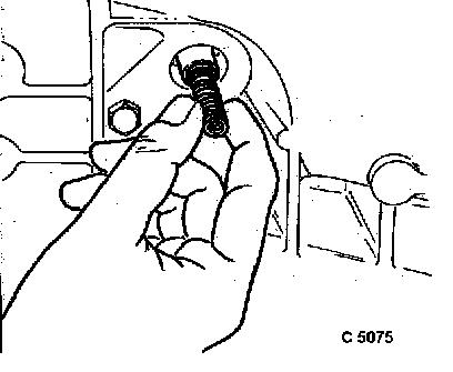
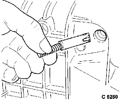
Remove locking bolt with pressure spring from front section of
transmission housing.
|
|
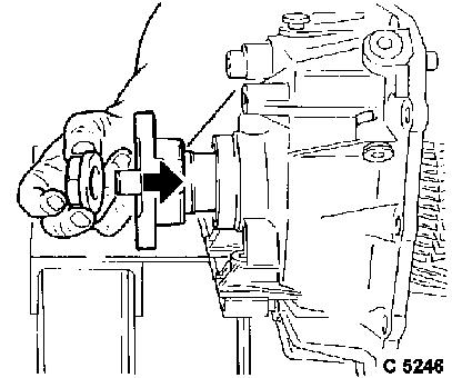
|
Remove retaining ring from bearing of main drive gear.
|
|
|
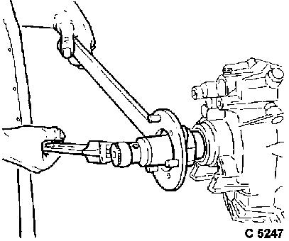
Output shaft flange from transmission, counterhold with KM-623
and unscrew using hex socket (size 30, extra long).
|
|
|
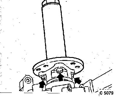
Turn transmission vertically downwards. Install KM-628-A with 3
screws to output shaft flange (arrows).
|
|
|
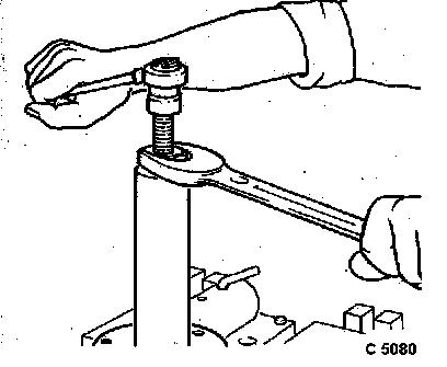
Screw KM-628-A in flush – counterhold at hex and remove
output shaft flange.
|
|
|
Turn transmission to horizontal position.
Unscrew fastening bolt for reverse idler gear shaft.
|
|
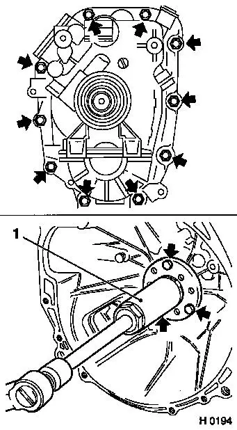
|
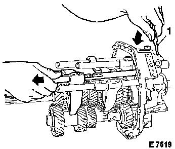
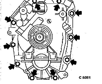
10 fastening bolts for transmission nose piece (arrows).
Install
Fasten KM-628-A (1) to transmission housing with central release
fastening bolts.
Remove
Remove transmission housing from transmission nose piece using
KM-628-A, bearing for main drive gear remains in housing.
|
|
|
Cover for stop balls from transmission.
Caution
Cover under spring pressure.
Remove
Pressure springs from transmission.
|
|
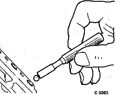
|
3 stop balls from transmission using bar magnet.
|
|
|
Grooved pins for shift forks using
drift.
|
Shift fork, 1st/2nd gear (1),
|
|
Shift fork, 3rd/4th gear (2),
|
|
Shift fork, 5th/reverse gear (3).
|
|
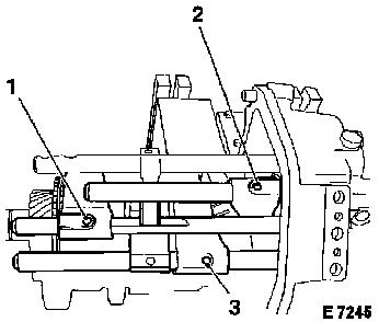
|
|
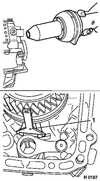
Pull shift rods out of shift forks, remove shift rods from
transmission nose piece.
If necessary, twist shift shaft (1) so that shift finger does
not handicap removal of shift rods.
|
|
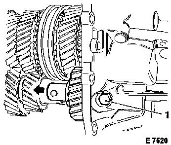
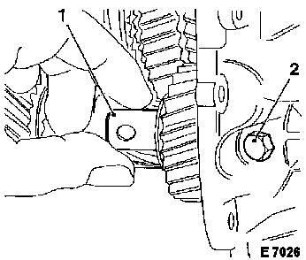
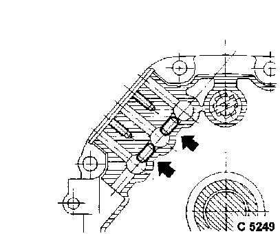
|
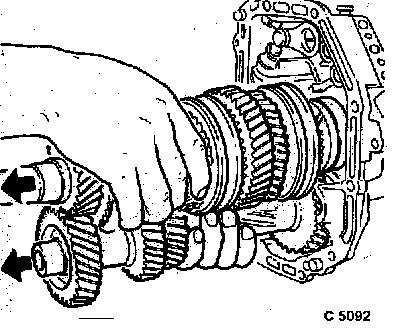
Fastening screw for reverse idler shaft (1) from transmission
nose piece, pull out reverse idler shaft slightly and remove with
reverse gear in direction of arrow.
|
|
|
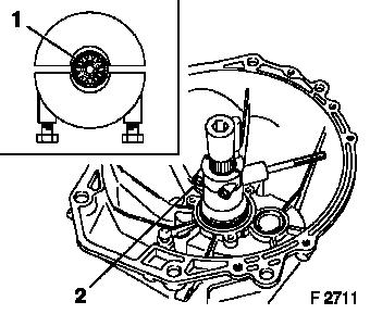
Compress retaining ring for main shaft bearing with KM-627. Hold
retaining ring tensioned – apply KM-627-1-A from above.
|
|
|
Heat transmission nose piece in area of main shaft bearing seat
to approx. 100 °C/212 °F using industrial hot air
blower.
Check temperature with thermocolour pencils or suitable
temperature gauge.
|
|
|
Remove main shaft and auxiliary shaft gear cluster from
transmission nose piece.
|
|
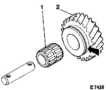
Install
|
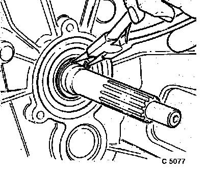
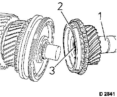
Install main drive gear (1) with synchroniser ring (2) and
bearing cage (3) onto main shaft.
|
|
|
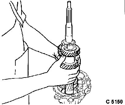
Assemble auxiliary shaft gear cluster and main shaft.
Assembled main shaft with auxiliary shaft gear cluster in
transmission nose piece.
|
|
|
Heat transmission housing nose piece in area of bearing seat to
approx. 100 °C/212 °F, industrial hot air blower,
thermocolour pencils or suitable temperature gauge.
Caution
Position of retaining ring. Do not jam retaining ring at
transmission nose piece. Insert KM-627-1 (1) opposite rocker on
retaining ring.
|
|
Remove
|
Remove KM-627-1 (2) from retaining ring (3) – remove
tensioner, adjust with retaining ring pliers (1) so that retaining
ring engages in groove.
Install
Drive new seal ring for output shaft flange into transmission
nose piece with KM-629-1 (4).
|
|
|
Drive shaft flange onto teeth of main shaft, insert new
fastening nut with locking compound.
|
|
Torque
|
Counterhold drive shaft flange with KM-623 – hexagon
wrench (A/F 30, extra long) – 150 Nm / 111 lbf. ft.
|
|
Install
|
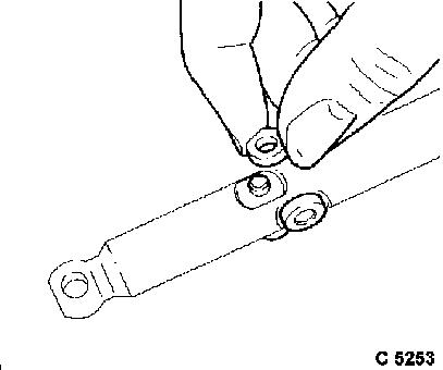
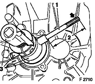
Install double-row needle roller bearing (1) in reverse idler
gear (2). Insert reverse idler gear in transmission. Identification
groove (arrow) points to driving direction.
|
|
|
Push reverse idler gear shaft (1) through until rear screw (2)
can be inserted into nose piece.
Torque
Reverse idler gear shaft to transmission – 22 Nm / 16 lbf.
ft.
|
|
Install
|
Coat 2 locking pins for gearshift rods with lubricating grease
and insert with bar magnet into transmission nose piece.
|
|
|
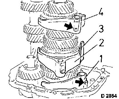
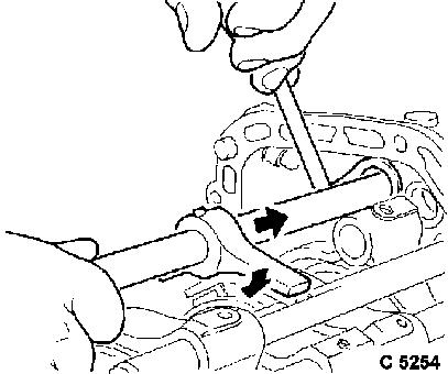
All shift forks onto respective sliding sleeve:
5th/reverse shift fork (1): Recognisable by offset, the rounded
heel (arrow) points to the drive side.
1st/2nd shift fork (2): Lubricating duct (3) points to the drive
side.
3rd/4th shift fork (4): Shift fork has no offset, the rounded
heel (arrow) points to the output side.
|
|
|
Push 1st/2nd shift rod with shift driver through shift fork and
place in transmission nose piece. Align bore holes for grooved
pin.
Caution
All sliding sleeves are in idle position.
|
|
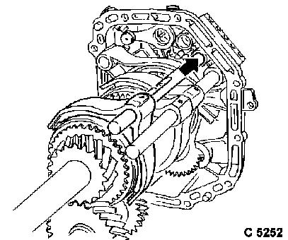
Install
|
Install 3rd/4th shift rod in shift fork, so that recesses point
away from 1st/2nd shift rod. Insert 3rd/4th shift rod in centre
bore hole in transmission nose piece, so that bore holes for
grooved pins align.
|
|
|
Place 4 rollers on shift lever shaft and adhere by inserting
with lubricating grease.
|
|
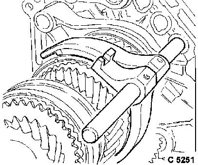
Caution
|
Install shift lever shaft with shift finger into selector rocker
in transmission nose piece.
Position of shift finger, turn selector rocker slightly if
necessary.
|
|
Install
|
5th/reverse shift rod into shift fork and transmission nose
piece, so that bore holes for grooved pin are aligned.
|
|
|
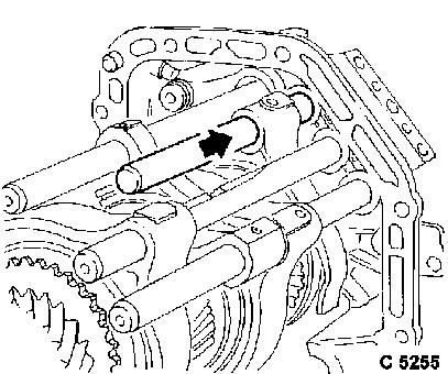
Drive 3 grooved pins (1, 2, 3) into shift forks and shift rods
using KM-308.
Caution
Support shift rod ends (e.g. using wooden block). Drive in
grooved pins, so that they protrude approx. 1 mm/0.04 in.
|
|
Install
|
Insert 3 locking balls and 3 pressure springs into transmission
nose piece.
Torque
Cover – install with sealing compound at transmission nose
piece (2 bolts) – 10 Nm / 7.5 lbf. ft.
Install
Closure plugs (arrow) for locking pins at transmission nose
piece – drive in fluid-tight with plastic hammer.
Drive in seal ring for shift lever shaft flush with KM-629-3
(1). Turn transmission to vertical position. Engage 4th gear.
Caution
All synchroniser rings must be loosely seated. Loosen firmly
seated synchroniser rings from cone of gear.
|
|
Install
|
Apply sealing compound to sealing surface of transmission nose
piece.
Front section of transmission housing to transmission nose
piece. Ensure that shift rods are inserted correctly into bore
holes in transmission.
Ball bearing with retaining ring to main drive gear.
|
|
|
Place bushing KM-461-3 (1) on drive shaft, lubricate moving
parts of Tool KM-461-C. Screw holder rod into KM-461-C to stop.
Slide KM-461-C with holder rod over bushing KM-461-3 and tighten
bolts (2).
|
|
|
Length (2) of holder rod (1) can be varied by screwing into or
out of the thread.
Unscrew holder rod (1) from KM-461-C until end of holder rod
lies on a reinforcement rib (arrow).
Heat transmission housing in bearing seat area to approx. 100
°C. Use industrial hot air blower and thermocolour pencils or
suitable temperature gauge.
Press ball bearing flush to retaining ring in front section of
transmission housing using KM-461-C (3) by turning on square drive
shaft (1/2").
|
|
|
Retaining ring to main drive gear, retaining ring pliers.
Put transmission into idle position.
 Inspect
Ensure that output flange can be turned in all transmission
gears.
|
|
Torque
|
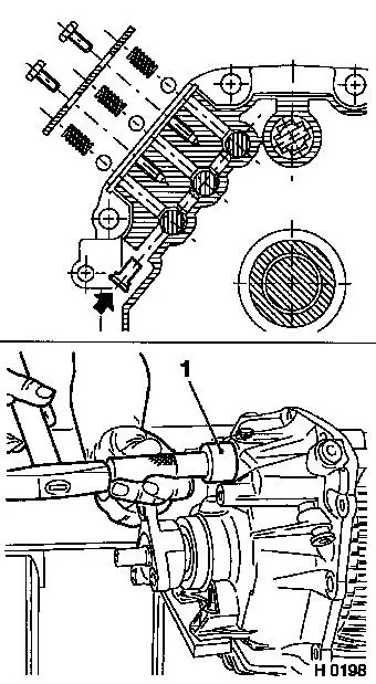
Install 10 screws (arrows) of transmission nose piece – 22
Nm / 16 lbf. ft.
|
|
|
Front screw (arrow) of reverse idler gear shaft – 22 Nm /
16 lbf. ft.
|
|
Install
|
Pre-install vent line (1) to central release.
Torque
Central release to transmission (3 screws, 3) – 22 Nm / 16
lbf. ft.
Attach pressure line (2) with grommet
and bolt to central release – 14 Nm / 10 lbf. ft.
|
Vent line (1) to central release – 14 Nm / 10.5 lbf.
ft.
|
|
Vent line to vent line – 9 Nm / 6 lbf. ft.
|
|
|
|
Install
Retaining plate (arrow) for vent line.
|
|
|
Pressure spring (white marking) and pin (with roller in
horizontal position) into transmission.
Drive in cover using plastic mallet. For widened bore hole, an
oversized cap is available.
|
|
Torque
|
Switch for reversing lamps with spacer (1) – 20 Nm / 15
lbf. ft.
|
|
Install
|
Install connecting piece (2) with outer shift rod, install pin
and retaining clamp (1). Folding cover.
Torque
Fluid drain bolt (2 in illus. E 7517) – 30 Nm / 22 lbf.
ft.
|
|
|
Top up transmission fluid up to 9 mm beneath the fluid filler
bore hole (1) – approx. 1.2 litres – see also operation
"Fluid Level, Check and Correct". Fluid quality – see
"Technical Data".
Torque
Fluid filler plug – 30 Nm / 22 lbf. ft.
Remove transmission from KM-113-2 and KM-622.
|
|
Install
Installing transmission - see operation "Removing and installing
manual transmission (vehicles with 4-cylinder petrol engine)",
"Removing and installing manual transmission (X 20 DTH, Y 22 DTH)",
"Removing and installing manual transmission (25 DT, X 25 DT)",
"Removing and installing manual transmission (Y 25 DT) or "Removing
and installing manual transmission (vehicles with V6 engine)".
|
