|
Steering Gear, Remove and Install (Vehicles with
Diesel Engine)
 Remove Remove
|
For vehicles with air conditioning and Y 25 DT engine: Drain air
conditioning – see operation "Air Conditioning, Drain " in
group "D".
Detach ground cable from battery. Remove front wheel on driver's
side. Remove lower engine compartment cover.
|
|
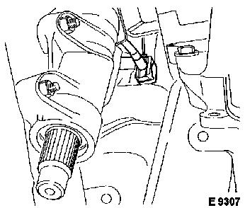
Detach protective cap from steering arm shaft.
|
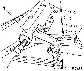
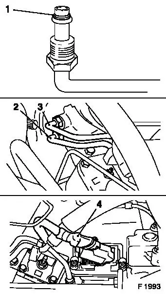
Detach fastening nut and washer for steering arm from steering
arm shaft. Mark steering arm to steering arm shaft installation
position. Remove steering arm using KM-146-01 (1) and move to one
side.
|
|
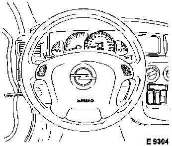
Caution
|
Vehicles with airbag: Turn steering wheel to straight-ahead
position, remove ignition key and allow steering and ignition lock
to engage.
|
|
Remove
|
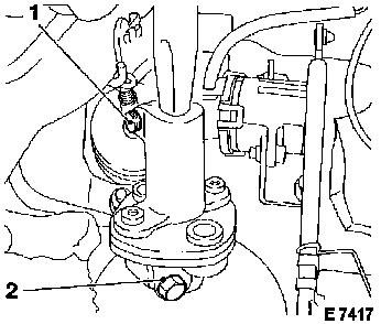
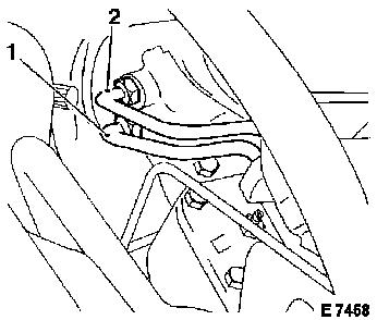
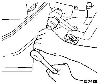
Remove driver's side footwell panelling. Loosen clamp bolts (1 +
2) from disc joint. Mark clamping piece position on the steering
arm shaft at a suitable location. Slightly widen disc joint
clamping pieces and slide onto steering shaft as far rearwards as
possible.
|
|
|
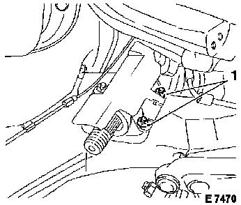
For vehicles with LHD and ABS 2 SH/TC: Disconnect wiring harness
plug (1) for ABS/TC control unit.
|
|
For Y 25 DT: Remove brake master cylinder and brake servo
– see operation "Brake Master Cylinder, Remove and Install or
Replace" and "Brake Servo, Remove and Install or Replace" in group
"H". In addition, on vehicles with air conditioning disconnect the
air conditioning line above the steering gear.
|
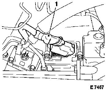
Release upper fastening bolt for heat shield of steering
gear.
Remove pressure line (1) and return line (2) from steering
gear.
Caution
Fluid escapes, collect and close off openings.
|
|
Remove
|
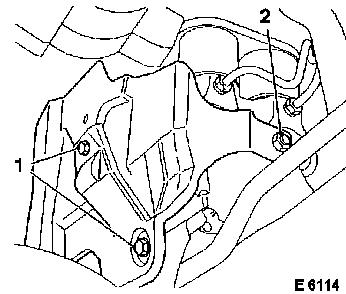
For vehicles with LHD and ABS 2 SH/TC: Release fastening bolts
(1) and fastening nut (2) for heat shield of hydraulic modulator
and remove heat shield.
|
|
|
Unfasten fastening nuts (1) for steering gear heat shield and
remove heat shield.
|
|
|
Disconnect wiring harness plug for electro-hydraulic
converter.
|
|
|
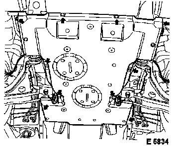
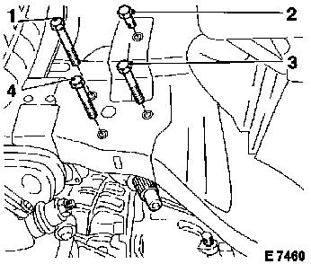
Remove fastening bolts (1-4) from steering gear – note
different bolt lengths and shims between wheel well and steering
gear under fastening bolt (2). Pull steering gear from disc joint
and remove downwards, at the same time carefully bend hydraulic
hose slightly to the side, do not damage.
|
|
For Replacement of Steering Gear (Vehicles up to
MY '96):
Due to a change to the steering gear from MY '96, the following
operations are to be carried out prior to installation:
|
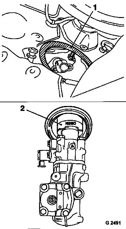
After removal of steering gear, the seal (1) at the bulkhead
must be removed – this operation must be carried out with
great care, as it may otherwise lead to the ingress of water and
passenger compartment noise in the area of the bulkhead.
Prior to installation of steering gear, the new bulkhead seal
(2) is to be aligned with the designation "OBEN" on the
identification plate and pushed onto the steering gear.
|
|
 Install
|
Insert steering gear into engine compartment by turning and
insert in clamp of disc joint.
Attach and tighten fastening bolts (1-4) for steering gear in
the following sequence: 1-4-3 – tightening torque 55 Nm / 41
lbf. ft. Insert fork-shaped shim between wheel well and steering
gear until the gap between wheel well and steering gear is closed
at fastening bolt (2). Attach fastening bolt (2) and tighten
– tightening torque 55 Nm / 41 lbf. ft.
|
|
|
Connect wiring harness plug for electro-hydraulic converter.
|
|
Vehicles without airbag:
|
Attach steering arm to steering arm shaft as marked –
tightening torque 160 Nm / 118 lbf. ft.
|
|
Connect heat insulation to steering gear – tightening
torque 15 Nm / 11 lbf. ft.
|
For vehicles with LHD and ABS 2 SH/TC: Attach heat shield to
hydraulic modulator with fastening nut (2) and fastening bolts (1)
– tightening torque 8 Nm / 6 lbf. ft.
Install lower engine compartment cover.
|
|
Vehicles with airbag:
Release steering and ignition lock.
|
Attach steering arm as marked to steering arm shaft using
fastening nut and washer – tightening torque 160 Nm / 118
lbf. ft. Attach protective cap.
|
|
Connect heat insulation to steering gear – tightening
torque 15 Nm / 11 lbf. ft.
|
For vehicles with LHD and ABS 2 SH/TC: Attach heat shield to
hydraulic modulator with fastening nut (2) and fastening bolts (1)
– tightening torque 8 Nm / 6 lbf. ft.
Install lower engine compartment cover.
|
|
All vehicles:
|
Replace O-rings (1) for pressure and return line.
Connect pressure line (2) and return line (3) to steering gear
– tightening torque 28 Nm / 21 lbf. ft.
For vehicles with left hand drive and ABS 2 SH/TC: Attach wiring
harness plug (4) for ABS/TC control unit.
|
|
For vehicles with air conditioning and Y 25 DT engine: Connect
air conditioning line above steering gear.
For Y 25 DT: Install brake master cylinder and brake servo
– see operation "Brake Master Cylinder, Remove and Install or
Replace" and "Brake Servo, Remove and Install or Replace" in group
"H".
Slide disc joint onto steering gear and attach clamping bolts to
steering gear and steering shaft – observe previously applied
mark – tightening torque 22 Nm/16 lbf. ft.. Install footwell
panelling.
 Inspect
Charge and bleed hydraulic system – see operation
"Hydraulic System, Charge and Bleed".
For vehicles with air conditioning and Y 25 DT engine: Charge
air conditioning – see operation "Air Conditioning, Evacuate
and Charge" in group "D".
|
