|
Steering Column Assembly, Dismantle and Assemble
(Height Adjustable Steering Column Assembly)
Steering column assy. removed
 Remove Remove
|
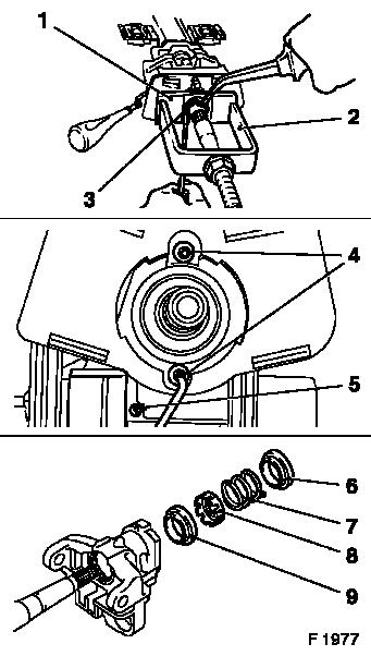
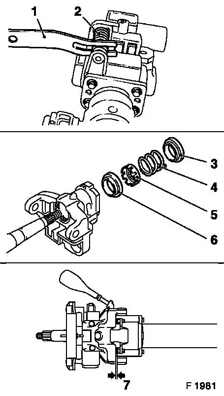
Compress pressure spring with KM-583-A (1) and KM-J-23653-A (2).
Remove snap ring (3) with screwdriver and sharp-nose pliers.
Unfasten both fastening screws (4) and remove signal switch
housing. Unfasten fastening screws (5), detach wiring harness plug
for steering and ignition lock.
Remove bearing race (9), pressure ring (8), pressure spring (7)
and depresser ring (6).
|
|
|
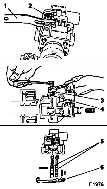
Remove pressure spring (2) for height adjustment using KM-584
(1).
Caution
Injury hazard when springs are released.
Remove
Pull both fulcrum bearing pins (4) out of bearing housing using
KM-585 (3). Remove bearing housing.
 Disassemble
Remove adjusting lever (6) and both detent levers (5) from
bearing housing.
|
|
|
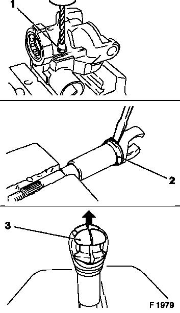
If necessary, drill out both shear bolts (1) for steering and
ignition lock housing with drill bit Ø 4.5 mm/0.18 in. and
remove with commercially available screwdriver. Remove steering and
ignition lock housing.
The bearing housing is available only as to assembly together
with both ball bearings.
When replacing the bearing housing, the bearing race (2) must be
replaced.
Disassemble universal joint (3) of steering shaft. If necessary
replace damaged parts.
|
|
 Assemble
|
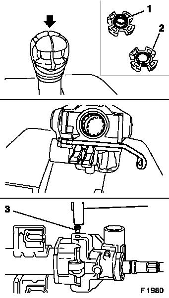
Assemble universal joint and install in steering shaft. For
this, the spring (1) must be seated in the recess (2) in each half
of joint. If removed, press on new bearing race.
 Install
If removed, fit new housing for steering and ignition lock with
shear bolts. Fit new fastening screw using locking compound (do not
micro-encapsulate). Install adjusting lever and both stop
buffers.
Install steering shaft in steering column. Install bearing
housing with both fulcrum bearing pins (3). Apply punch at 3 points
around circumference of each.
|
|
Assemble
|
Remove pressure spring (2) for height adjustment using KM-584
(1).
Install bearing race (6), pressure ring (5), pressure spring
(4), and depresser (3) onto steering shaft.
Install
Install signal switch housing (2 screws) and wiring harness plug
(1 threaded pin) for steering and ignition lock. Install retaining
ring.
Caution
When replacing the bearing housing with both ball bearings, the
gap (7) between the housing and the two stop buffers in the
uppermost steering wheel lock position must be checked. Compensate
differences with new stop buffers, which are available in different
thicknesses. The parts must fit exactly without the steering wheel
being able to move any further.
|
|
|
