|
Hydraulic Valve Lifter, Remove and Install
 Remove Remove
|
|
Remove camshaft - see operation "Camshaft, Remove and
Install".
Remove injection lines - see operation "Injection Lines, Remove
and Install".
Caution
Lay aside injection nozzle traverse, valve bridges and hydraulic
valve lifters in the correct order on removal to ensure correct
allocation on reinstallation.
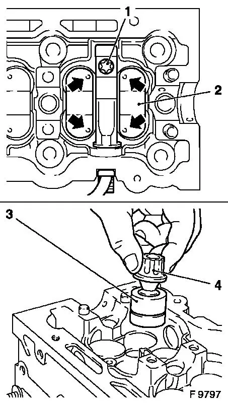
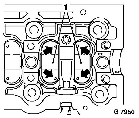
Remove fastening bolt (1) and slightly raise injection nozzle
traverse and then withdraw it forwards out of cylinder head.
Remove valve bridge (2) from cylinder head - note installation
position. Marks (arrows) on valve bridges are on the injection
nozzle traverse side.
Remove hydraulic valve lifters (3) from cylinder head with
KM-845 (4).
|
|
Remove
|
|
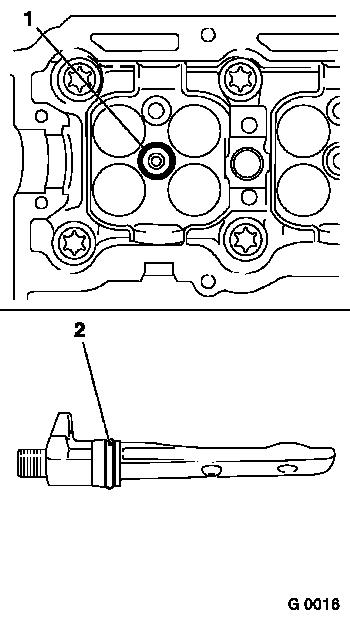
Detach seal ring (1) from injector nozzle.
|
|
 Inspect
Clean all removed parts, check for wear and replace if
necessary.
 Install
Attach new seal ring (1) to injection nozzle.
Lightly coat hydraulic valve lifters with clean engine oil and
insert in correct sequence in cylinder head.
Attach new seal ring (2) to injector nozzle traverse.
Caution
To prevent damage to gasket, it is essential that KM-6318 is
used.
Install
|
|
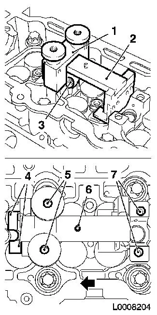
Position KM-6318-2 (2) above 2nd camshaft bearing (3) - ensure
that the sliding surfaces (4) are facing the engine timing
side.
Attach KM-6318-1 (1) to the 2nd camshaft bearing - make sure
that the bores (7) of the camshaft bearings and bolts (5) of
KM-6318-1 match up correctly. The stop (6) must be located on the
transmission side of KM-6318-1. Slide KM-6318-2 (2) in direction of
arrow until stop bears against KM-6318-1.
|
|
Install
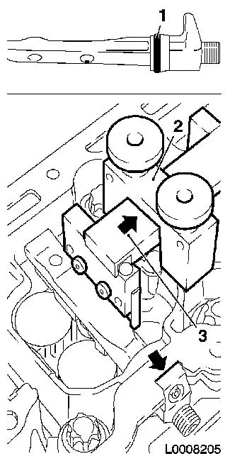
Apply a thin coat of silicone grease (white) to new seal ring
(1).
Carefully insert injection nozzle traverse of cylinders 1 and 2
until it bears against cylinder head (arrow) - if necessary assist
the process by tapping lightly with a plastic hammer.
Caution
Ensure that no dirt gets into the injection nozzle traverse as
this can result in operating faults.
Remove
|
|
Slide KM-6318-2 (3) in direction of arrow, detach KM-6318-1 (2)
from 2nd camshaft bearing and remove KM-6318-2.
|
|
Note: Repeat the
installation of the injection nozzle traverse with KM-6318 on
cylinders 3 and 4.
Caution
Only by following the tightening procedure described below can
it be guaranteed that the injection nozzle traverse is correctly
attached to the injection nozzle.
|
|
Install
|
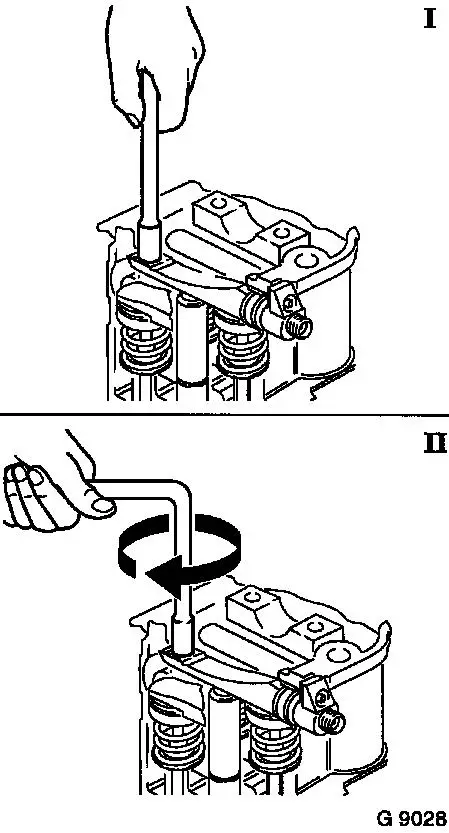
Insert traverse injection nozzle with new fastening bolt:
|
|
I.
|
with Torx nut and extension (without toggle or ratchet) hand
tighten fastening bolt,
|
|
II.
|
and then turn further by 360°.
|
|
|
Install
|
|
Insert valve bridges (1) into cylinder head - note installation
position - marks (arrows) on valve bridges are located on side of
traverse injection nozzle.
Install injection lines - see operation "Injection Lines, Remove
and Install".
Install camshaft - see operation "Camshaft, Remove and
Install".
|
|
Caution
Bleed fuel system with KM-948 once it has been opened.
|
