|
Camshaft, Remove and Install
 Remove Remove
|
|
Lock engine at 1st cylinder TDC - see operation "Engine, Lock at
1st Cylinder TDC (Timing, Check)".
As of MY '98: Detach power steering pump fluid reservoir from
air cleaner housing and place to one side.
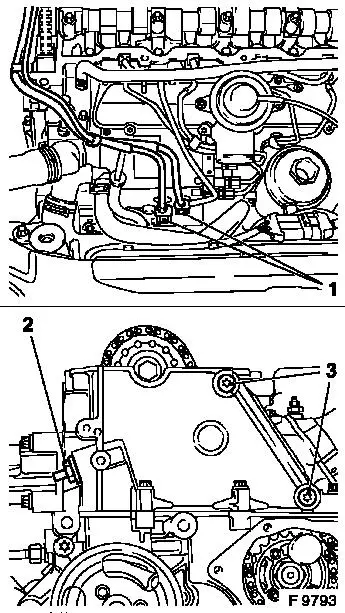
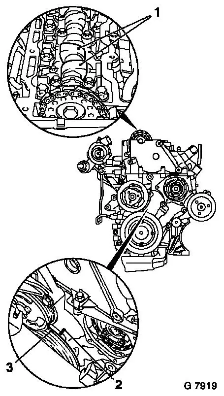
Detach fuel lines (1) from fuel injection pump and put to one
side (to rear).
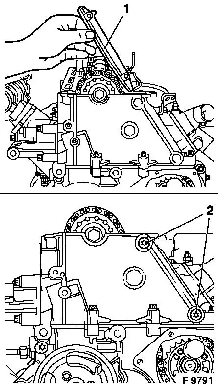
Remove simplex chain tensioner (2) - note installation
position.
Heat fastening bolts (3) intensively with hot air blower and
remove.
Caution
Use sheet metal plate or suitable heat shielding to avoid
damaging the guide rails.
Remove
Remove guide rail for Simplex timing chain upwards - note
installation position.
|
|
Caution
|
|
Remove Test Gauge KM-932 from cylinder head and Injection Pump
Lock Pin KM-927 from lock bore.
Remove
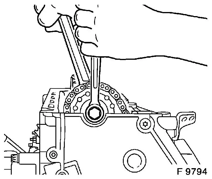
Remove camshaft sprocket from camshaft - counterhold with
open-ended wrench on hex of camshaft.
Note: To simplify
installation, suspend simplex timing chain at suitable point.
|
|
Caution
|
|
Note marking before dismantling camshaft bearing cover!
The camshaft must release evenly from the bearing seats.
|
|
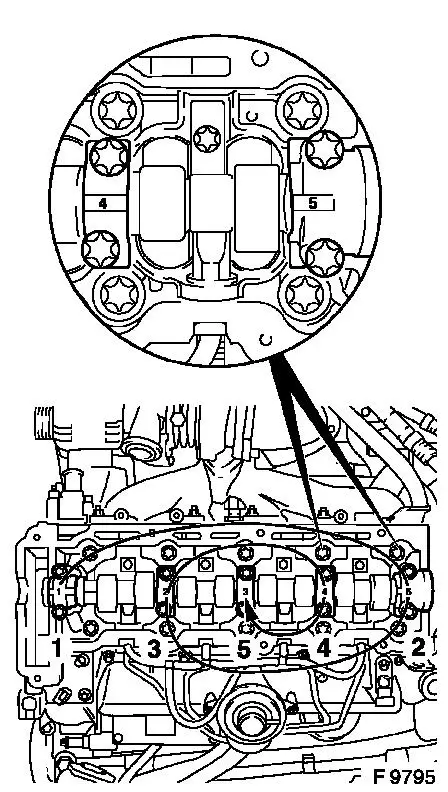
Remove
Release camshaft bearing cover in spiral pattern in steps of 1/2
to 1 turn in sequence illustrated.
Detach camshaft bearing caps from cylinder head and remove
camshaft.
Caution
When replacing camshaft, valve bridges must be replaced - see
operation "Valve Bridges, Remove and Install". Note installation
position of valve bridges - marks on valve bridges are located on
side of injection nozzle traverse.
 Clean Clean
Remove gasket remnants and clean sealing surfaces.
 Inspect
|
|
Check camshaft and bearing seat for wear and replace if
necessary.
|
|
 Install
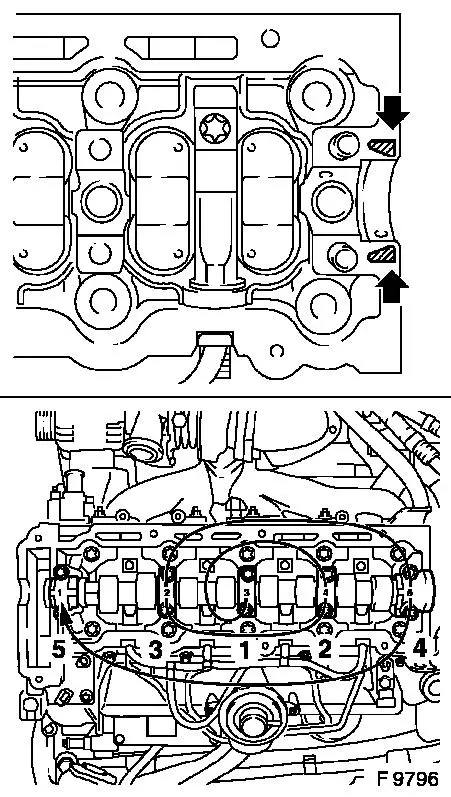
If valve bridges are being replaced - note installation
position. Marks on the valve bridges are on the injection nozzle
traverse side..
Apply surface seal (green) to sealing surfaces (arrows).
Coat sliding surfaces of valve bridges and camshaft with MoS
2 lubricating paste (grey). Insert camshaft
into cylinder head.
Caution
Note identification on camshaft bearing caps!
Install
Attach camshaft bearing caps to cylinder head and tighten using
spiral pattern in steps of 1/2 up to 1 turn in sequence illustrated
- tightening torque 15 Nm / 11 lbf. ft.
Install
Insert camshaft sprocket in simplex timing chain.
|
|
Attach camshaft sprocket with new fastening bolt to camshaft and
tighten by hand.
|
|
Caution
Ensure that camshaft sprocket is seated squarely on camshaft -
camshaft sprocket must sit flat against camshaft.
Install
Insert and attach Simplex timing chain guide rail (1) with new
fastening bolts (2), clean thread beforehand - ensure correct
installation position - tightening torque 8 Nm / 6 lbf. ft.
Inspect
|
|
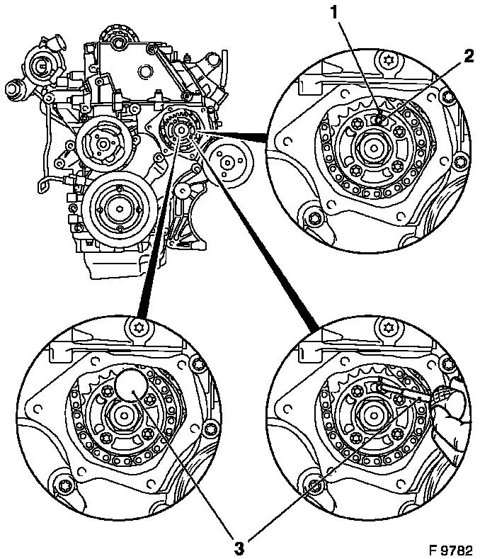
Arrow (1) on Simplex injection pump gear must be aligned with
the recess in injection pump flange and retaining bore (2) in
injection pump.
|
|
Install
Insert Injection Pump Lock Pin KM-927 (3) in lock bore of fuel
injection pump.
Install
|
|
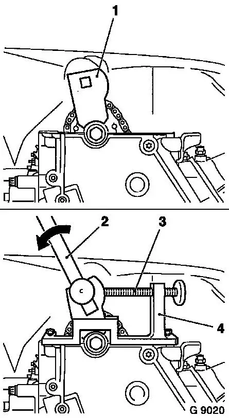
Insert carrier (1) of Adjuster KM-933 (4) vertically into
camshaft sprocket.
Install Adjuster KM-933 on cylinder head.
|
|
 Adjust Adjust
Use handle (2) to exert slight pressure on the carrier in the
direction of arrow (counter engine rotational direction) and fix in
place with holder bolt (3).
Removal and installation of Retaining Pin KM-927 for fuel
injection pump must be possible under suction. If this is not
possible, the pressure on the adapter plate must be slightly
reduced using the adjustment screw (3).
Install
Attach camshaft sprocket to camshaft with new fastening bolt -
tightening torque 90 Nm / 66 lbf. ft. + 60° + 30°.
Install
|
|
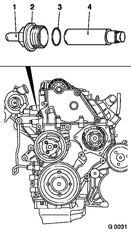
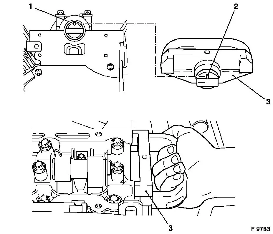
Insert simplex chain tensioner (4) in cylinder head - closed
side of chain tensioner must face tension rail. Install closure
bolt (2) with new seal ring (3) - tightening torque 60 Nm / 44 lbf.
ft.
Caution
When installing a new Simplex chain tensioner, chain tensioner
must be released by means of release bolt (1) after assembly. Push
in release bolt with hammer handle until click is audible.
It must be possible to push in release bolt up to stop with
thumb and for it to slide back to its original position
automatically - the release bolt can no longer be pushed in once
the oil pressure has built up.
|
|
Remove
|
|
Remove all locking and adjusting tools.
|
|
Adjust
At the torsional vibration damper fastening bolt, turn
crankshaft slowly and smoothly for two rotations (approx. 720°)
in direction of engine rotation until just in front of 1st cylinder
ign. TDC - mark (3) on torsional vibration damper is located just
in front of timing case lug (2).
Inspect
In this position, the cams (1) of the 1st cylinder are just
before TDC (both cams point upwards).
Install
|
|
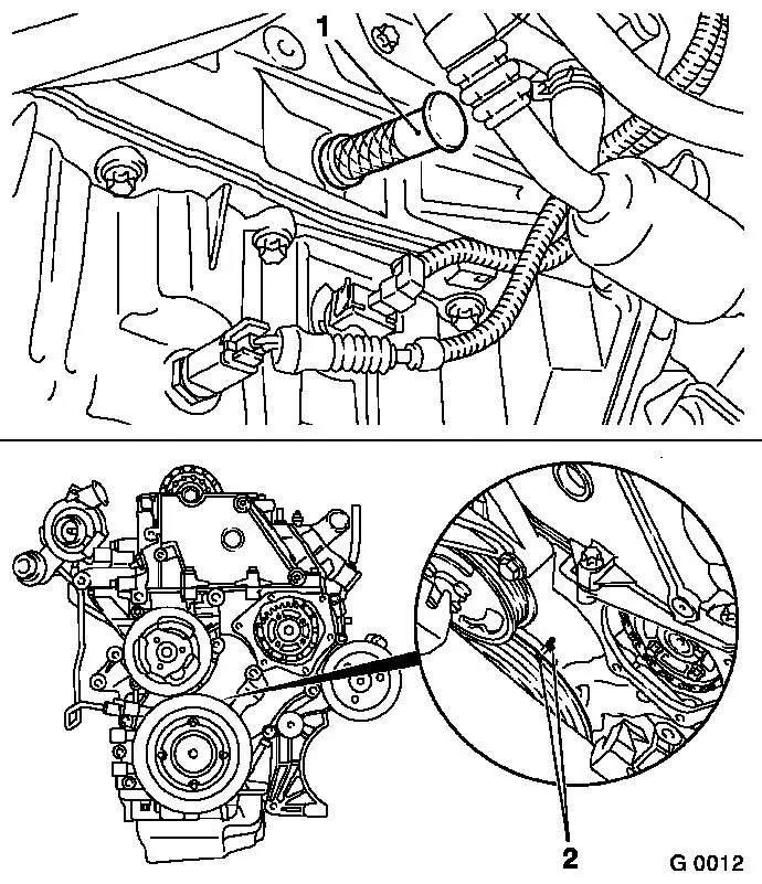
Insert Crankshaft Lock Pin KM-929 (1) in crankshaft pulse
pick-up aperture and simultaneously continue turning crankshaft
slowly and smoothly in direction of engine rotation using fastening
bolt for torsional vibration damper so that crankshaft retaining
pin engages to the stop in cylinder block or crank web.
|
|
Inspect
In this position, the marks (2) must be aligned.
Inspect
|
|
Arrow (1) on Simplex injection pump gear must be aligned with
the recess in injection pump flange and retaining bore (2) in
injection pump.
|
|
Install
Insert Injection Pump Lock Pin KM-927 (3) in lock bore of fuel
injection pump.
Install
|
|
Apply Test Gauge KM-932 (3) to cylinder head - pin (2) must
engage in bore (1) of camshaft.
|
|
Remove
|
|
Remove all locking tools.
|
|
Clean
Clean sealing surfaces on timing case cover and timing case -
cover aperture in timing case with lint-free cloth.
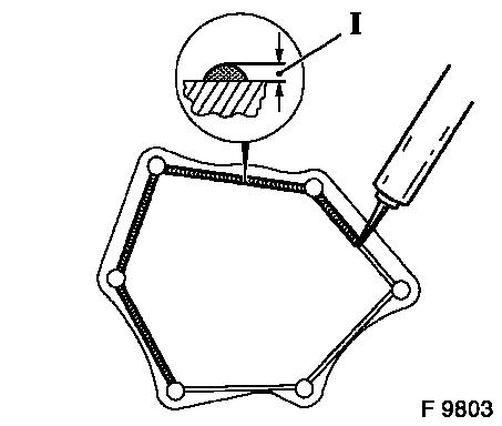
Install
Apply an approx. 2 mm (Dimension I) thick bead of silicone
sealing compound (grey) to timing case cover.
Caution
The application of silicone sealing compound (grey),
installation of timing case cover and tightening to torque must be
performed within 10 minutes.
Install
Attach timing case cover to timing case with new fastening bolts
- secure using 2 threaded bolts (M6) - tightening torque 6 Nm / 4.5
lbf. ft.
Install
Attach crankshaft pulse pick-up to cylinder block with new seal
ring - tightening torque 8 Nm / 6 lbf. ft.
Lower engine using engine bridge and attach engine damping block
bracket to engine damping block - tightening torque 45 Nm / 33 lbf.
ft.
Connect front exhaust pipe to return manifold with new gasket
and new fastening nuts - tightening torque 20 Nm / 15 lbf. ft.
Connect front exhaust pipe to muffler - tightening torque 12 Nm
/ 9 lbf. ft.
Install ribbed V-belt tensioner - see operation "Ribbed V-belt
Tensioner Assembly, Remove and Install".
Install vacuum pump - see operation "Vacuum Pump, Remove and
Install".
Attach fuel lines to injection pump with new seal rings -
tightening torque 15 Nm / 11 lbf. ft.
As of MY '98: Attach power steering pump fluid reservoir to fan
housing.
Install cylinder head cover - see operation "Cylinder Head
Cover, Remove and Install".
Note: Before
assembling components of the intake system (hoses, connections,
etc.), they must be cleaned of any possible contamination (grease,
oil, etc.). When tightening the hose clamps, be sure to observe
exactly the tightening torque of 3.5 Nm / 2.6 lbf. ft.
Caution
It is only ensured that the intake system is free of leaks, thus
ensuring operational safety of the engine, if the hose clamps are
tightened correctly to the prescribed tightening torque.
Install
Install air cleaner housing with hot film mass air flow meter
and air intake hose - see illustration "Air Cleaner Housing, Air
Duct".
Note: Bleed fuel
system with KM-948 once it has been opened.
|
