Engine, Remove and Install
 Important! Important! Fuel escapes - observe safety measures and national legislation. Collect escaping fuel in a suitable container.
 Remove, Disconnect Remove, Disconnect For X 16 SZR and 16 LZ2: remove fuel pump relay - see operation "Fuel Pump Relay, Remove and Install". Start engine for at least 5 sec - fuel pressure reduction. For 20 NEJ: reduce fuel pressure with Fuel Pressure Manometer KM-J-34730-91 via testing port - collect escaping fuel in suitable container. Remove front panelling - see operation "Front Panelling, Remove and Install" in group "A". For 20 NEJ: remove air cleaner housing and air intake hose - see illustration "Air Cleaner Housing, Air Flow Guide (20 NEJ)". Detach or remove all wiring harness plugs from Motronic M 1.5.4 - see illustration "Cable Routing - Motronic M 1.5.4". For X 16 SZR and 16 LZ2: remove air cleaner housing, air intake hose and air intake cover - see illustration "Air Cleaner Housing, Air Flow Guide (X 16 SZR)" or "Air Cleaner Housing, Air Flow Guide (16 LZ2)". Detach or remove all wiring harness plugs from Multec central fuel injection - see illustration "Cable Routing - Multec Central Fuel Injection". Remove wiring trough from camshaft housing cover and from alternator - lay wiring trough with cable bundle to one side.
Remove, Disconnect Disconnect positive terminal from battery, positive cable (2) from positive terminal and ground cable (5) from ground terminal. Disconnect multiple plug (4) (rotary catch). Detach relay frames (1), (3) and (6) from bracket and lay aside. Remove battery. Remove ground cable (7). Disconnect multiple plug (8) (turning lock). Remove lower coolant hose from radiator - collect escaping coolant. Remove all coolant hoses from coolant compensation tank and lay to the side. Remove retaining bracket (9), left and right from air deflector panel. Version without air conditioning: Separate air flow guide, left and right from radiator. | 
|
Remove, Disconnect Detach torque support (1) with torque support bracket (2) and remove. Detach coolant hoses (5) from heater core - release catch ring (4) of coolant hose in direction of arrow and disconnect from heater core. For version with air conditioning: drain air conditioning - see operation "Air Conditioning, Drain" in group "D". Remove refrigerant line block connection (3) from expansion valve and lay upwards out of the way. | 
|
Remove, Disconnect For X 16 SZR and 16 LZ2: Detach throttle valve actuation Bowden cable (1) and place to one side. Disconnect vacuum line (2) to intake pipe pressure sensor from throttle valve injection housing. Remove fuel lines (3) from throttle body. Detach vacuum hose (4) from tank vent valve - when detaching the vacuum hose from the valve body, ensure that the valve connections are not damaged. Damaged valves must be replaced. Close off vacuum hose to activated carbon canister.
Important! Damaged valve connections may lead to vehicle fires as a result of leaks.
Remove, Disconnect Remove brake servo vacuum line (5) from intake manifold. | 
|
Remove, Disconnect For 20 NEJ: Detach fuel lines from fuel distributor pipe and from fuel pressure regulator. Detach brake servo vacuum line (1) from intake manifold. Detach throttle valve actuation Bowden cable (2) from throttle body and lay aside. For version with manual transmission: detach delivery connection for hydraulic clutch actuation from manual transmission and seal line. Release clamp from shifter rod and detach shift guide from shifter rod. For version with automatic transmission: detach wiring harness plug (3) from selector lever position switch and wiring harness plug (4) from transmission wiring harness. Press selector lever actuation cable off from control lever for selector lever shaft. | 
|
Important! Vehicles with airbag: Turn steering wheel to driving straight ahead position, remove ignition key and let steering wheel lock engage.
Remove, Disconnect Remove intermediate steering spindle clamp bolt (1) (passenger compartment). Remove front exhaust pipe. Remove right and left swing arm (2) from spring strut support tube - counterhold with open-ended wrench at the two flattened areas. Pull axle shafts out of wheel hubs - see operation "Axle Shaft, Remove and Install" in group "E". | 
|
Remove, Disconnect Construct Base Frame KM-904 (2) with Centring Mount KM-905 (1) on hydraulic jack and place without clearance under front axle body (use hydraulic jack which can be lowered to at least 100 cm).
Important! Removal with pulse or impact screwdriver not permitted. Note different bolt lengths and washers. | 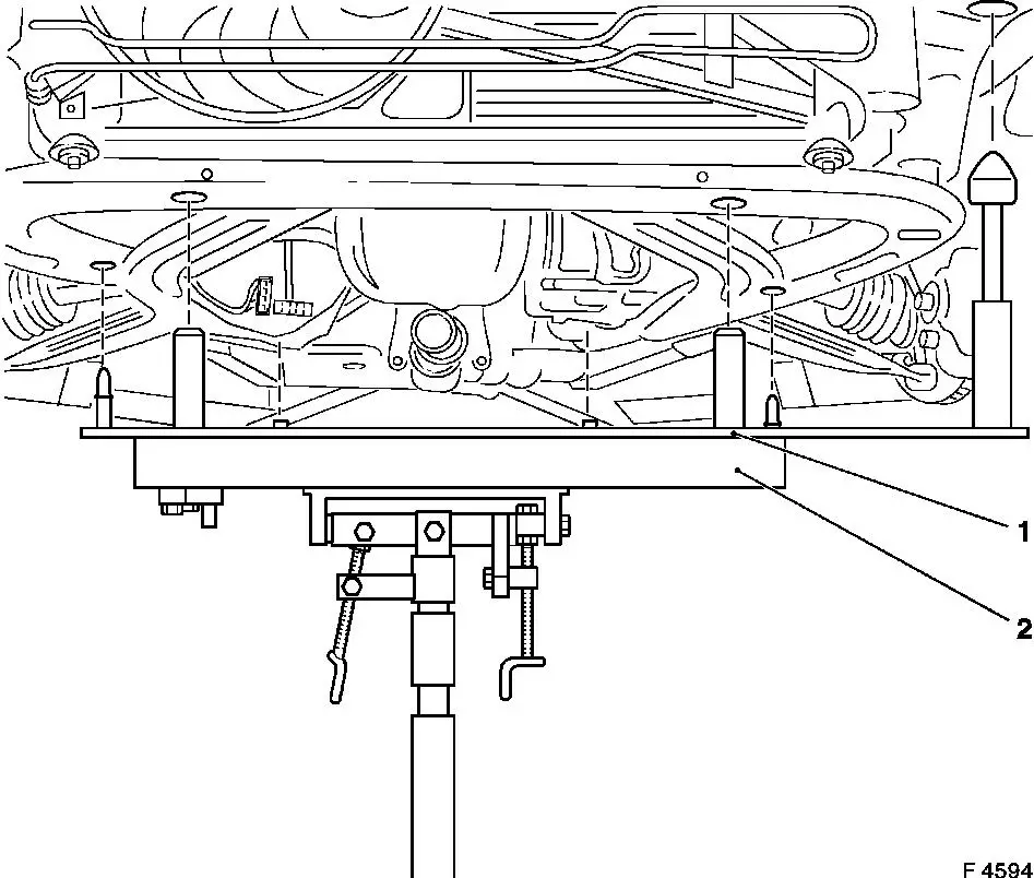
|
Notice: For clearer representation, illus. F8464 shows the front axle body without the hydraulic jack and centring mount.
Remove, Disconnect Remove fastening bolts (1) (4 off). Remove fastening bolts (2) (4 off). Remove fastening bolts (3) (2 off). Carefully lower front axle body with entire drive unit, steering gear and radiator - thereby ensuring that no attaching parts are damaged.
Important! Before installing front axle body with drive unit: check thread of locking nuts (fastening bolts 1-3) for ease of movement, replace locking nuts if necessary - see operation "Replacement Locking Nuts" in group "A". | 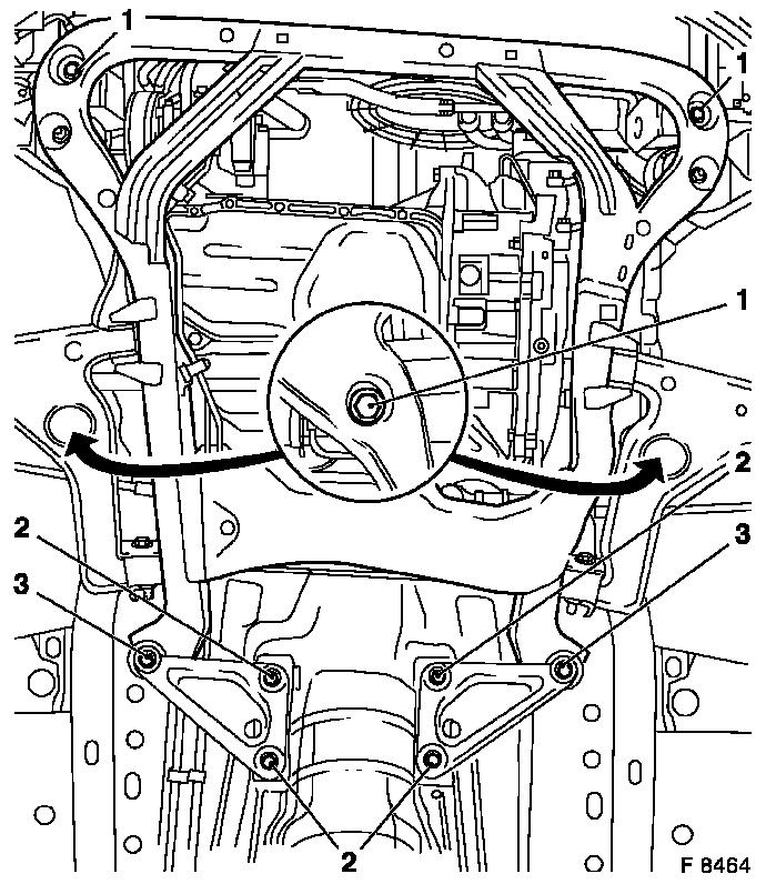
|
 Install, Connect Install, Connect Carefully insert front axle body with entire drive unit, steering gear and radiator in engine compartment and position free of play on chassis - use hydraulic jack, Base Frame KM-904 and Centring Mount KM-905. Thereby ensure that no attaching parts are damaged. Attach front axle body with new fastening bolts to chassis - note different bolt lengths (1 and 3: long bolts, 2: short bolts) - tightening torque 100 Nm / 74 lbf. ft. + 45 ° + 15 ° 1) 2)
. Use torque wrench and KM-470-B.
Important! Removal with pulse or impact screwdriver not permitted. Note different bolt lengths and washers. |
|
1) Use new fastening bolts. 2) Insert fastening bolts with screw locking compound (red). The installation time including torque check is max. 5 min.
Install, Connect Install axle shafts in wheel hub - see operation "Axle Shafts, Remove and Install" in group "E". Attach swing arms on both sides to spring strut support tube with new fastening nuts - counterhold with an open-ended wrench at two flattened points - tightening torque 65 Nm / 48 lbf. ft. Install front exhaust pipe. Attach steering intermediate shaft to steering gear (interior) - tightening torque 22 Nm / 16 lbf. ft. + 45 ° + 15 ° 1) . Version with AT: Connect wiring harness plug to selector lever position switch and wiring harness plug to transmission wiring harness. Install selector lever actuation cable at actuating lever for selector lever shaft. For version with manual transmission: attach delivery connection for hydraulic clutch actuation to manual transmission. Attach shift guide to shifter rod - tighten to torque only after shift linkage has been adjusted.
1) Re-cut thread for steering intermediate shaft before re-use. Insert new fastening bolt with screw locking compound (red). The installation time including torque check is max. 5 min.
Install, Connect For 20 NEJ: attach fuel lines with new seal rings to fuel distributor pipe - tightening torque 15 Nm / 11 lbf. ft. Attach brake servo vacuum line to intake manifold - tightening torque 20 Nm / 15 lbf. ft. Attach throttle valve control Bowden cable to throttle body. For X 16 SZR and 16 LZ2: attach fuel lines to throttle body - tightening torque 15 Nm / 11 lbf. ft. Attach vacuum hoses to throttle body. Connect vacuum hose for the activated carbon filter to tank vent valve. Attach brake servo vacuum line to intake manifold - tightening torque 20 Nm / 15 lbf. ft. Attach vacuum hose for the intake pipe pressure sensor to throttle valve injection housing. Connect throttle valve control Bowden cable. Attach refrigerant line block connection to expansion valve (bulkhead) - tightening torque 10 Nm / 7 lbf. ft. Attach coolant hoses to heater core and lock. Attach torque support with torque support bracket to cylinder block adapter and bracket - 60 Nm / 44 lbf. ft.
Install, Connect Version without air conditioning: Install air guides, left and right to radiator. Install retaining bracket (9), left and right at air deflector panel. Install all coolant hoses at coolant compensation tank. Install lower coolant hose at radiator. Connect multiplug (8) (bayonet catch). Attach ground cable (7). Install battery. Connect relay frames (1), (3) and (6) to bracket. Connect multiplug (4) (bayonet catch). Connect positive terminal to battery, attach positive cable (2) to positive terminal and ground cable (5) to ground terminal. Install front panelling - see operation "Front Panelling, Remove and Install" in group "A". |
|
Install, Connect Attach cable trough to camshaft housing cover - tightening torque 8 Nm / 6 lbf. ft. Attach wiring trough bracket or cable bundle to alternator - X 16 SZR: 20 Nm / 15 lbf. ft., 16 LZ2 and 20 NEJ: 18 Nm / 13 lbf. ft. Notice: Before assembling components of the intake system (hoses, connections, etc.), they must be cleaned of any possible contamination (grease, oil, etc.). When tightening the hose clamps, be sure to observe exactly the tightening torque of 3.5 Nm / 2.6 lbf. ft.
Important! It is only ensured that the intake system is free of leaks, thus ensuring operational safety of the engine, if the hose clamps are tightened correctly to the prescribed tightening torque.
Install, Connect For X 16 SZR and 16 LZ2: connect or attach all wiring harness plugs for Multec central fuel injection - see illustration "Cable Routing - Multec Central Fuel Injection". Install air cleaner housing, air intake cover and air intake hose - see illustration "Air Cleaner Housing, Air Flow Guide (X 16 SZR)" or "Air Cleaner Housing, Air Flow Guide (16 LZ2)". Install fuel pump relay - see operation "Fuel Pump Relay, Remove and Install". For 20 NEJ: connect or attach all wiring harness plugs for Motronic M 1.5.4 - see illustration "Cable Routing - Motronic M 1.5.4". Install air cleaner housing and air intake hose - see illustration "Air Cleaner Housing, Air Flow Guide (20 NEJ)".
Install, Connect For version with AC: Charge AC - see operation "Air Conditioning, Evacuate and Charge" in group "D". Version with MT: bleed clutch hydraulics - see operation "Clutch Hydraulics, Bleed" in group "K". Adjust transmission shift linkage - see operation "Transmission Shift Linkage, Adjust" in group "K". Top up cooling system - see operations "Cooling System, Top up and Bleed" and "Cooling System, Check for Leaks".
|
