Main Shaft, Dismantle and Assemble (F 15/F 17) Notice: Transmission remains installed.
 Remove, Disconnect Remove, Disconnect Remove shift cover (1) - see operation "Shift Cover, Disassemble and Reassemble (F 13/F 15/F 17/F 18/F 18+)". Remove reversing lamps switch (2). Remove end shield cover (3) - see operation "Gasket for End Shield Cover, Replace (F 13/F 15/F 17/F 18/F 18+)". Remove end shield (4) from transmission - see operation "Gasket for End Shield, Replace (F 13/F 15/F 17/F 18/F 18+)". | 
|
Remove, Disconnect Remove main shaft - see operation "End Shield with Main Shaft and Drive Shaft, Remove and Disassemble (F 15/F 17)".
 Disassemble Disassemble Press 1st speed gear from main shaft with KM-307-B (2) and KM-736 (1). Remove sleeve (3), ball bearing (4), pressure washer (5), output shaft (6) and retaining ring (7). Remove synchroniser rings for 1st gear, comprising inner synchroniser ring (8), outer synchroniser ring (10) and intermediate ring (9). Remove retaining ring for 1st/2nd gear synchromesh body with KM-396 (11). | 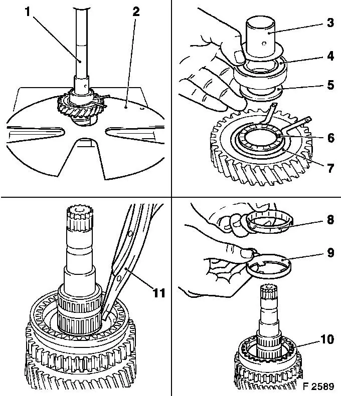
|
Disassemble Press 1st/2nd gear synchromesh body assembly and 2nd speed gear (1) from main shaft - supporting 2nd speed gear on recesses of press support plates. Remove 1st/2nd gear synchromesh body assembly (2) and 2nd gear synchroniser ring (6) - detach outer synchroniser ring (3), intermediate ring (4) and inner synchroniser ring (5). Remove retaining ring (7) for thrust washer and both thrust washer halves (arrow) from main shaft. Detach 3rd speed gear (8). Detach slotted needle bearing (9) and 3rd gear synchroniser ring (10). Remove retaining ring for 3rd/4th gear synchromesh body with KM-396 (11) - remove spacing ring located underneath from synchromesh body. | 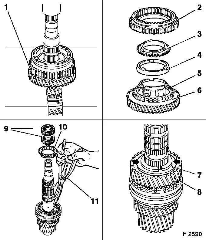
|
Disassemble Press 3rd/4th gear synchromesh body assembly from main shaft - supporting 4th speed gear (4) on recesses of press support plates. Remove 3rd/4th gear synchromesh body assembly (2) and 4th gear synchroniser ring (3) from 4th gear. Detached slotted needle bearing (5) from main shaft. Drive thrust washer (arrow) evenly from main shaft with suitable mallet and soft metal drift.
 Clean Clean Clean all parts.
 Inspect Inspect Check removed parts for damage and wear. | 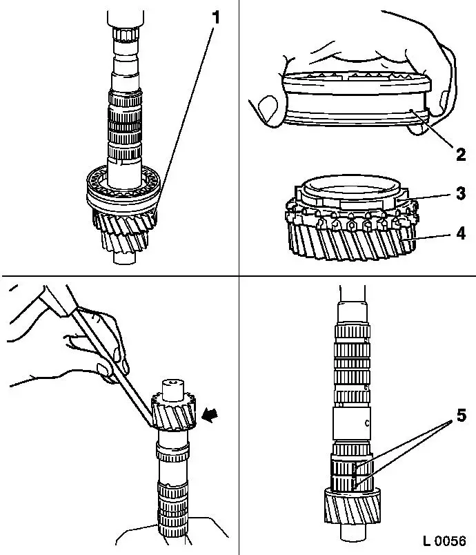
|
Notice: Coat all parts with transmission fluid before assembly. Check parts for wear, signs of scoring, damage; if necessary replace.
 Important! Important! If gears are damaged, always check the gears of the gear cluster and replace gear cluster if necessary.
Notice: If a synchromesh body assembly has been completely disassembled then the following method of procedure shall be observed for assembly.
 Assemble Assemble Insert synchromesh body (3) into shifter collar (2). Insert slide blocks (1 and 5) with the open end toward synchromesh body. Insert synchroniser spring (4); ensure that the correct end of synchromesh body raises (arrow) for correct installation position. If this is not the case, turn synchroniser spring 180 ° and reinstall. Offset end of synchroniser engages in a slide block. | 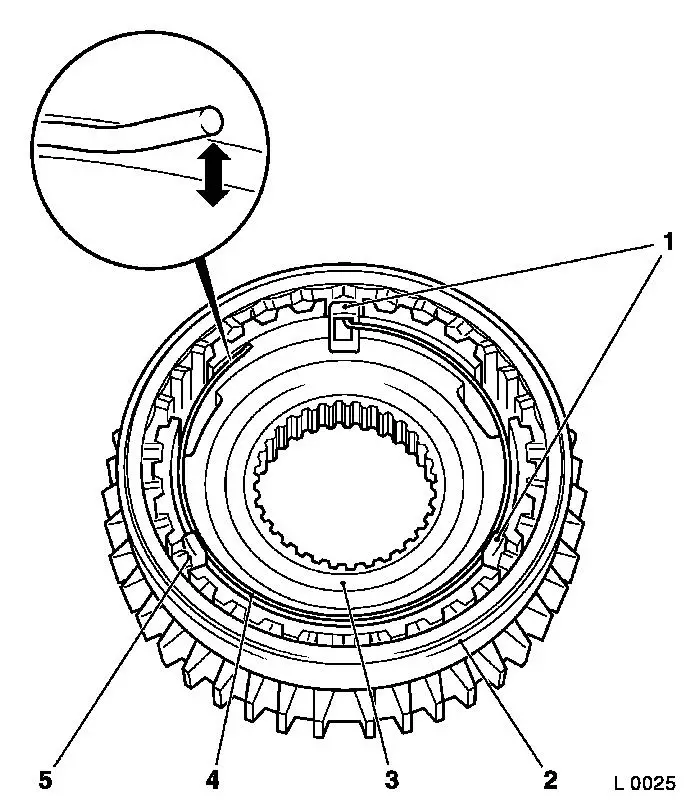
|
Assemble Press thrust washer (2) on main shaft in conjunction with KM-307-B (1). Attach slotted needle bearings (3) to main shaft. Position 4th gear synchroniser ring (5) and synchromesh body assembly (4) on 4th speed gear (6).
Important! Side of slider sleeve with groove (arrow) points to 4th speed gear.
Assemble Press 3rd/4th gear synchromesh body assembly (8) with synchroniser ring and 4th speed gear (7) onto main shaft so that lugs of synchroniser ring align with grooves in synchromesh body. | 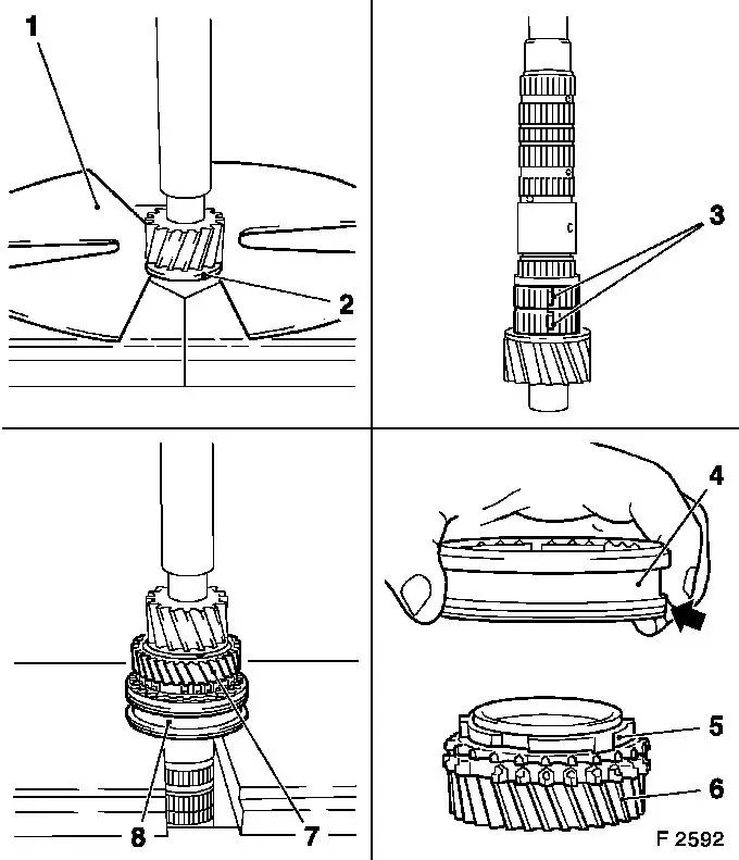
|
Assemble Place spacer ring on synchromesh body and attach new retaining ring with KM-396 (3) - ensure that the retaining ring is correctly seated in the groove. Attach 3rd gear synchroniser ring (2) on synchromesh body assembly and slotted needle bearing (1) on main shaft. Place 3rd speed gear (5) on main shaft. Mount both halves of thrust washer (arrows) and retaining ring (4). Attach synchroniser rings and synchromesh body assembly (6) onto 2nd gear (10) - outer synchroniser ring (9), intermediate ring (8) and inner synchroniser ring (7). Press 1st/2nd gear synchromesh body assembly (12) with 2nd speed gear (11) onto main shaft so that lugs of outer synchroniser ring align with grooves in synchromesh body. | 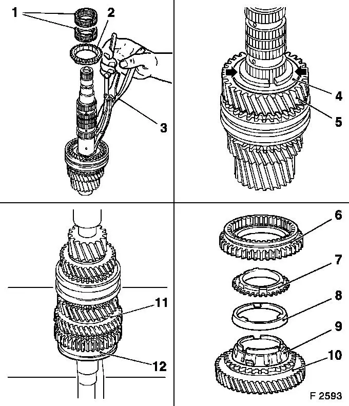
|
Assemble Insert retaining ring (1) for 1st/2nd gear synchromesh body with KM-396. Place 1st gear (2) with synchroniser rings (inner synchroniser ring, intermediate ring and outer synchroniser ring) on 1st/2nd gear assembly - ensure that lugs in outer synchroniser ring align with grooves in synchromesh body. Attach new retaining ring, output shaft and pressure washer onto 1st speed gear. Press ball bearing with KM-258 (3) onto main shaft. Press sleeve (5) onto main shaft with KM-258 (4).
Inspect All gears must turn freely. Install main shaft - see operation "End Shield with Main Shaft and Drive Shaft, Disassemble and Reassemble (F 13/F 15/F 17/F 18/F 18+)". | 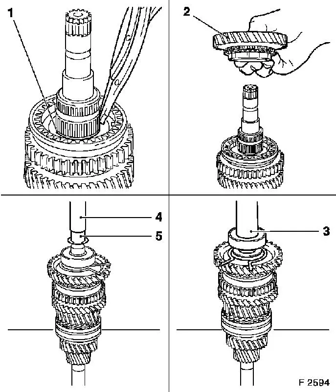
|
 Install, Connect Install, Connect Install end shield (1) in transmission - see operation "Gasket for End Shield, Replace (F 13/F 15/F 17/F 18/F 18+)". Install gasket for end shield cover (2) - see operation "Gasket for End Shield Cover, Replace (F 13/F 15/F 17/F 18/F 18+)". Install reversing lamps switch (4) with new seal ring - tightening torque 20 Nm / 15 lbf. ft. Install shift cover (3) - see operation "Shift Cover, Disassemble and Reassemble (F 13/F 15/F 17/F 18/F 18+)".
Inspect Check transmission fluid level - see operation "Transmission Fluid Level, Check and Correct (F 13/F 15/F 17/F 18/F 18+)". | 
|
|
