Assemblies, Install in Transmission (F 25) General measures before assembly:
 Inspect Inspect Check all parts for wear and damage - damaged or defective parts must be replaced. Remove all sealant residue from separation surfaces. Coat all bearing and friction surfaces with transmission fluid before assembly.
 Install, Connect Install, Connect Place differential in clutch housing - aligning recess on differential with protrusion on drive axle bearing support (arrow). | 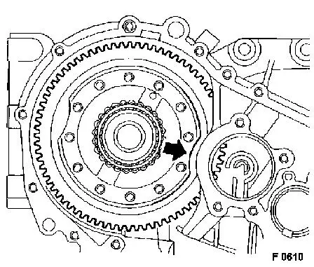
|
Install, Connect Insert guide sleeve (arrow). Insert main shaft into transmission housing. Apply main shaft bearing with a plastic mallet. Insert bearing support. Carefully drive bearing support in flush using KM-864 (3), KM-514 (2), KM-577 (1) and a plastic mallet. | 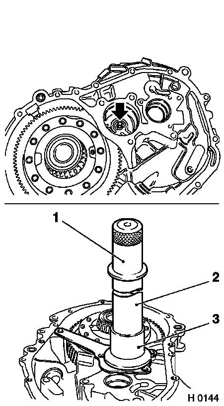
|
Install, Connect Attach bearing support (4 bolts) - tighten bolts alternately.
 Tighten (Torque) Tighten (Torque)
|
Outer bolt (arrow) - 22 Nm / 16 lbf. ft. |
|
Remaining 3 bolts - 40 Nm / 29.5 lbf. ft. |
Install, Connect Place synchroniser unit with shifted gears for 1st/2nd gear on main shaft with Assembly Device KM-860 (3). Place 3rd gear (2) and spacer sleeve (1) on main shaft.
 Important! Important! The installed gears must not slide too far onto the output shaft. About 15 mm/0.6 in. must be left to guarantee installation of the drive shaft. | 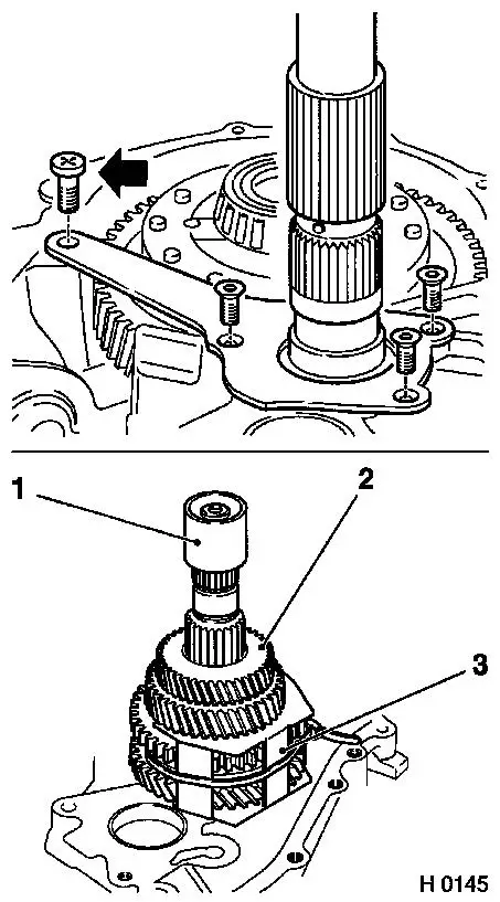
|
Install, Connect Insert drive shaft (2) in transmission housing. Install cable tie (1), holding drive shaft toothing (2) in mesh with main shaft toothing (3). Press down the gear wheels on the main shaft to the level of the clutch housing - if necessary drive in with KM-514 and a plastic hammer until the new tension sleeve (5) and the 4th gear (4) can be positioned with the rotating pinion upwards.
Important! Old clamping sleeve must be replaced by new one, as clamping effect is nullified on removal. | 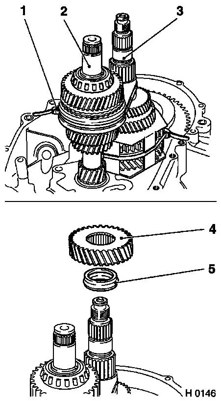
|
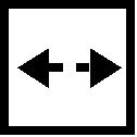
Install, Connect Attach KM-866 (1) to drive shaft and pull down until 4th gear and gears on the drive and main shafts are level (arrow). Cut open cable tie and take out KM-860 (2). Raise drive shaft slightly and install reverse idler shaft with reverse gear. Bore in reverse idler shaft must be aligned to bore in clutch housing. | 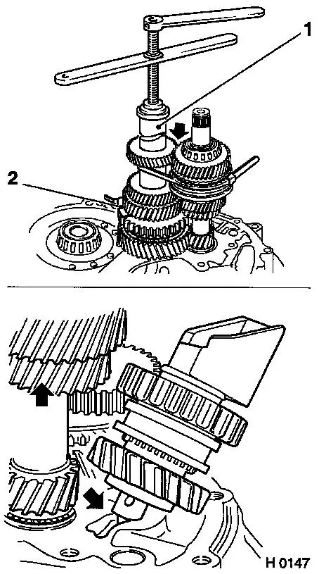
|
Install, Connect Install shift mechanism in clutch housing with 1st gearshift fork in 1st gear position. Guide 1st/2nd gearshift sleeve to shift level of 2nd gear on main shaft, press 3rd/4th gearshift sleeve into shift level for 4th gear on drive shaft. Place 1st/2nd and 3rd/4th gearshift forks in shift sleeves. Put shift mechanism into position by turning and sliding. Remove 1st gear by raising shift fork with a screwdriver. Insert guide sleeves (2) and bolt (1).
Tighten (Torque) Fit reverse gear guide lever (4) - the longer bolt (50 mm) is for the guide lever and the shift mechanism - tightening torque 22 Nm / 16 lbf. ft. Insert short bolts (3) with screw locking compound (red).
Important! Fluid baffle for shift linkage lever must be installed under edge on shift mechanism. | 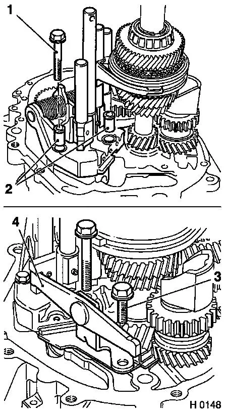
|
Install, Connect Install shift fork (1) on reverse-gear shift sleeve. Ensure that guide lever (arrow) fits into reverse-gear shift fork groove. Press in shift fork axle (2). Place reverse gear in shift mechanism. Insert shift rod (6) with a little transmission fluid. Insert shift rod - ensure that the small bore (5) (for the roll pin) in the fork for the shift guide points upwards. Insert driver (4), slide in shift rod and tighten the bolt (3) of the driver - 22 Nm / 16 lbf. ft. Try to shift each gear. Then engage the 3rd or 4th gear. | 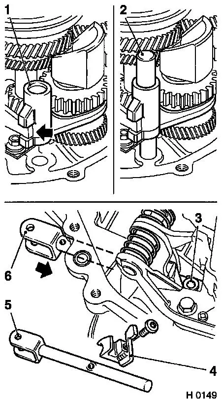
|
Important! If bearings on main shaft or differential have to be replaced, the sealing flange must be removed and the differential bearing inner races pressed out, so that the bearing pretension can be subsequently measured.
Install, Connect Sparingly apply sealing compound (black) to contact surface of transmission casing and clutch housing and allow to dry for a few minutes.
Important! Do not plug sintered body (arrow) in transmission vent with sealing compound, as otherwise fluid may be pressed out of transmission. | 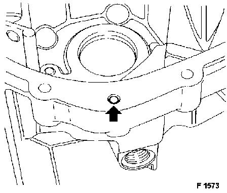
|
Important! Ensure that the reverse idler shaft mount is correctly seated, so that the bolt can be installed following installation of the transmission housing.
Install, Connect Place transmission housing on clutch housing.
Important! Cover openings in transmission housing to prevent foreign objects from getting into the transmission. | 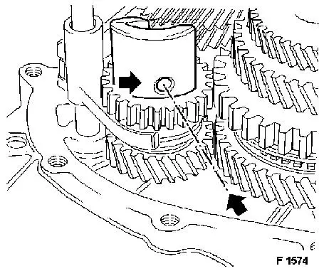
|
Install, Connect Fix transmission housing lightly on clutch housing with 2 bolts - do not draw down completely against tapered roller bearing outer race. Install bolt (2) for reverse idler shaft bearing - if necessary fix thread opening at opening in transmission housing with small screwdriver. Drive in guide sleeves with drift and appropriate mallet in direction of arrow. Insert bolts (1) in surface separating transmission housing and clutch housing. Install remaining bolts.
Tighten (Torque) Transmission housing to clutch housing - 22 Nm / 16 lbf. ft. | 
|
Install, Connect Place tapered roller bearing inner race on main shaft and carefully pull in with KM-866 (1).
Important! Do not draw tapered roller bearing inner race down onto tapered roller bearing outer race. There must be clearance apparent.
Install, Connect Press down gear of the 5th speed as required using plastic hammer and KM-514. Carefully pull down gear of the 5th speed with KM-866. Install new nut. Install control gear of the 5th speed with needle bearing, synchroniser and shift sleeve on drive shaft. The stop cams (arrows) of the synchroniser ring must lie in front of openings in hub. If necessary, drive hub on drive shaft with KM-514 and KM-577. | 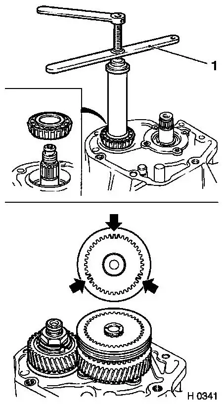
|
Install, Connect Install Dial Gauge MKM-882 with Bracket KM-875. Engage 3rd gear and press down 5th gearshift sleeve so that transmission is blocked.
 Adjust Adjust Slowly and evenly tighten nut, occasionally measuring end play with dial gauge - screw short bolt M8 into transmission housing and measure end play by levering between head of bolt and 5th speed, raise 5th speed sleeve. Continue adjustment procedure until axle play of 0.15 mm to 0.20 mm results.
Important! Do not measure directly under toothed part, apply dial gauge pointer correctly. Remove M8 bolt again. | 
|
 Measure Measure Shift transmission to neutral. Apply point of dial gauge probe to end of shaft. Install KM-876 on main shaft and turn transmission with a drill so that bearings settle. Press and pull with drill, repeat approx. 20 times. Remove tool. Note measured value for end play and add coefficient - push dial gauge aside.
|
Example: |
Measured value |
+ coefficient |
= nominal diameter. |
|
|
0.23 mm |
+ 0.20 mm |
= 0.43 mm |
|
|
|
|
|
Coefficient:
|
Old housing (greater than 50,000 km/30,000 miles) |
0.12 mm |
|
Old bearing (greater than 50,000 km/30,000 miles) |
0.12 mm |
|
Old housing (up to 50,000 km/30,000 miles) |
0.15 mm |
|
Old bearing (up to 50,000 km/30,000 miles) |
0.15 mm |
|
Old housing (up to and above 50,000 km/30,000 miles) and new bearing |
0.20 mm |
|
New housing and new bearing |
0.26 mm |
| 
|
Install, Connect Engage 3rd gear and press down 5th gearshift sleeve to block transmission.
Adjust Fit KM-877 (1) (mm-disc) on nut of main shaft. Mark one tooth on the gear. Adjust the degree setting of the tool to the calculated nominal value. | 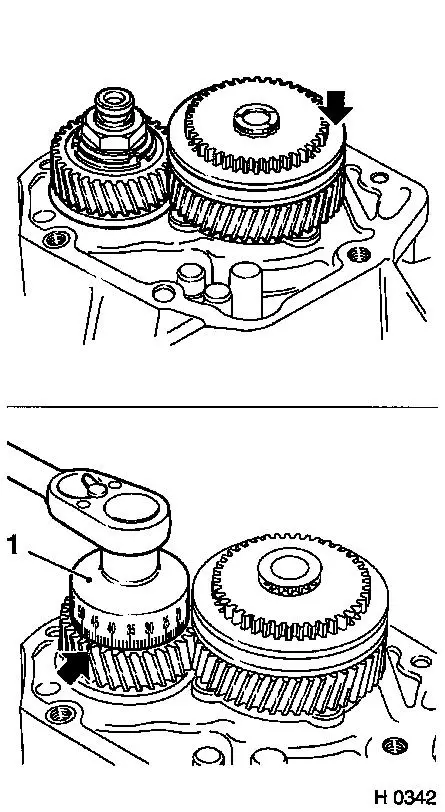
|
Adjust Tighten main shaft nuts in 2 or 3 stages until zero position of tool is at marked tooth. Swage outer nut collar at three places in 5th gear to secure nuts. Remove KM-877.
 Remove, Disconnect Remove, Disconnect Lift off 5th gear with needle bearing, synchronisation and shift sleeve from drive shaft - if necessary remove with KM-559-A. | 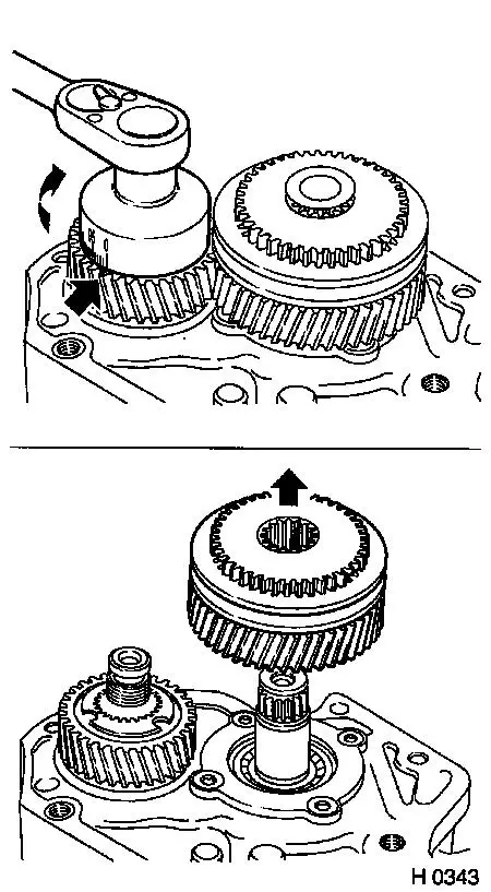
|
Inspect Check pretension of differential. If the main shaft bearing or the differential bearing has been replaced, the differential pretension must be checked and adjusted as follows: Position KM-878 instead of tapered roller bearing outer race. Install a spacing washer packet of about 1.2 mm/0.047 in. together with sealing flange (without O-ring).
Measure Engage 3rd gear. Place KM-879 (10 kg weight) (1) on the gasket flange. Fit KM-876 (2) onto the main shaft. Turn differential 20 times with drill. Measure the clearance at 3 points between the gasket flange and the transmission casing using a feeler gauge. Determine the average and adjust to the value below. | 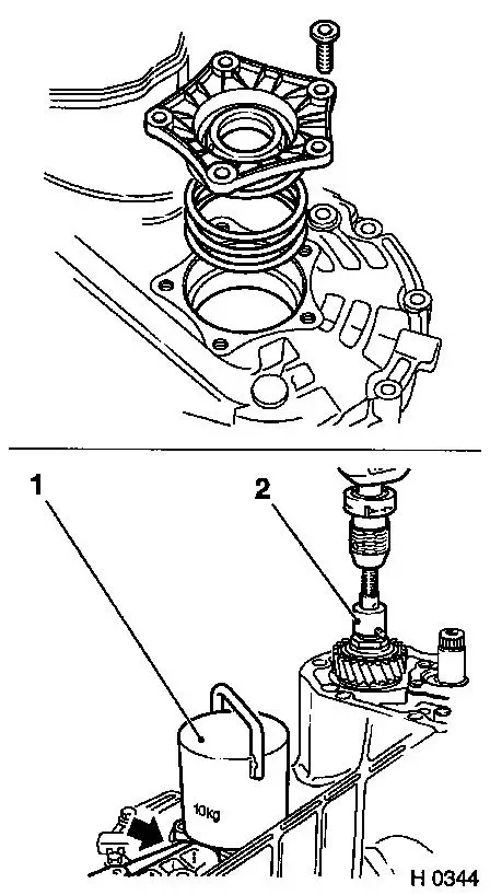
|
Adjust Specified value for differential:
|
Transmission housing |
load compartment area |
Coefficient |
|
Old (50,000 km) |
Old (50,000) |
0.20 |
|
Old (50,000 km) |
New |
0.30 |
|
New |
New |
0.35 |
|
Thicker spacing washers = increase pretension. |
|
Thinner spacing washers = reduce pretension. |
|
Spacer washers for the differential are available in the sizes of 0.10, 0.15, 0.30 and 0.50 mm. |
Remove, Disconnect Remove KM-879 (1). Replace KM-878 with tapered roller bearing outer race for differentials. Remove KM-877 (2).
Important! Do not forget to replace KM-878 with tapered roller bearing outer race, as otherwise transmission will be damaged. | 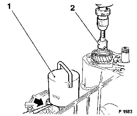
|
Install, Connect Place tapered roller bearing outer race for differential in transmission housing, drive in slightly with plastic mallet and, if necessary, with KM-864 (1).
Important! Do not drive tapered roller bearing outer race onto inner race.
Tighten (Torque) Install tapered roller bearing outer race, determined spacing washers and sealing flange (5 bolts). Tighten bolts alternately - 22 Nm / 16 lbf. ft.
Remove, Disconnect Remove KM-876. | 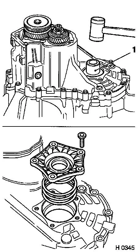
|
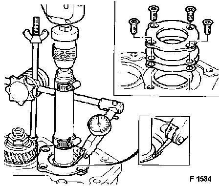
Install, Connect Install KM-880 on drive shaft. Position tip of dial gauge probe on bearing. Attach drill to tool and turn transmission until bearings settle. Press and pull with drill, repeat approx. 20 times.
Measure Measure end play - nominal value: 0.04 mm - 0.11 mm. If required, place spacing washer under bearing flange.
|
Thicker spacing washers = increase pretension. |
|
Thinner spacing washers = reduce pretension. |
|
Spacing washers for differential are available in the sizes 0.10, 0.15 and 0.30. |
| 
|
Adjust When adjusting the axial clearance of the drive shaft: Unscrew 4 bolts for the bearing flange. Re-fit gasket flange with the appropriate spacer washers. Tighten bolts alternately - 40 Nm / 30 lbf. ft. Check the axial clearance again.
Important! If end play is too low, the transmission housing must be removed and the bearing outer race pressed out again - repeat the operation. Remove tools. |
|
Install, Connect Engage 3rd gear, install shifted 5th gear with needle bearing, synchronisation and shift sleeve on drive shaft.
Important! Stop cams of synchroniser ring must lie in front of opening in hub. If necessary, drive hub onto drive shaft with KM-514.
Install, Connect Install 5th gearshift fork on shift sleeve. Drive new locking pin into 5th gearshift fork with drift. Install new retaining ring. | 
|
Tighten (Torque) Attach transmission cover to transmission housing with new gasket (7 bolts) - 22 Nm / 16 lbf. ft.
Inspect Shift through all gears to check shift mechanism.
Tighten (Torque) Install drain plug and seal thread with sealing compound - ensure that the magnet is positioned in the drain plug - 50 Nm / 37 lbf. ft. | 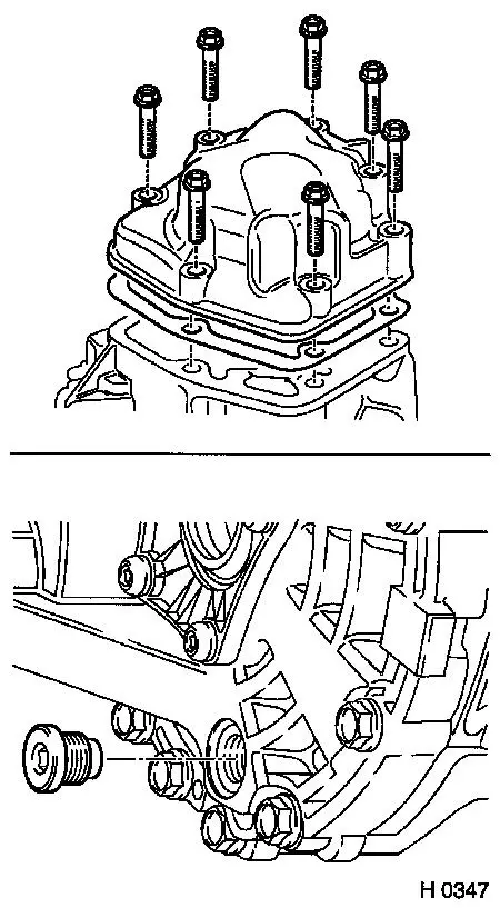
|
Install, Connect Install central release - see operation "Central Release, Remove and Install".
Tighten (Torque) Reversing lamps switch with new gasket to transmission - 22 Nm / 16 lbf. ft.
Remove, Disconnect Remove Transmission Bracket KM-622 from transmission. Install joint and fastening parts.
Install, Connect Install transmission - see operation "Transmission, Remove and Install - F 25". | 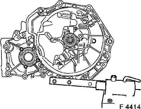
|
|
