Manual Transmission and Differential, Overhaul - F 25 Assemblies, Remove from Transmission
 Remove, Disconnect Remove, Disconnect Remove transmission - see operation "Transmission, Remove and Install - F 25" Drain transmission fluid, remove reversing lamp switch, joint and fastening parts. Secure Transmission Holder KM-622 (1) to transmission.
 Tighten (Torque) Tighten (Torque) Transmission bracket on transmission - 20 Nm / 15 lbf. ft. Remove central release - see operation "Central Release, Remove and Install". Remove transmission cover (7 bolts) and gasket. | 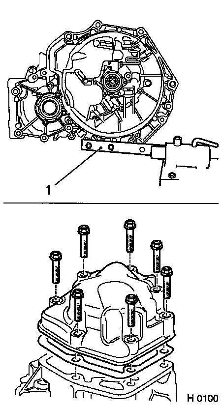
|
 Important! Important! Before removing the shift sleeve, mark the installation position of the shift sleeve and of the 5th gear synchromesh body with a marking pen. To prevent lock balls of shift mechanism falling out, block transmission by engaging 3rd or 4th gear.
Remove, Disconnect Drive out locking pin (1) of 5th gearshift fork (2) with suitable drift. Remove shift fork (2) and shift sleeve (3) for 5th gear.
 Install, Connect Install, Connect Place shift sleeve (3) on 5th gear synchromesh body again.
Important! Engage two gears simultaneously. Shift sleeve can only be pressed onto synchromesh body when longer splines on shift sleeve are located directly in front of synchromesh body groove. | 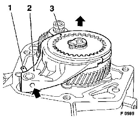
|
Remove, Disconnect Engage 5th speed - press down on shift sleeve (2). Release lock (arrows) with suitable screwdriver and unscrew nut (1). Remove retaining ring (3) of the 5th speed synchromesh body. Remove 5th speed synchromesh body (4) with 5th speed shift sleeve (5) and 5th speed gear (6) with KM-559-A from drive shaft. Remove needle bearing for 5th speed gear. Remove 5th speed gear (7) with KM-559-A from main shaft. | 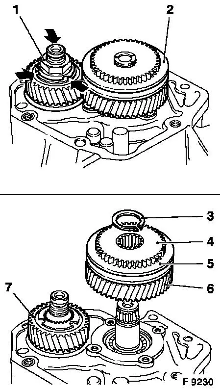
|
Remove, Disconnect Unscrew bolt (2) for reverse shaft bearing in transmission housing. Unscrew bolts in surface separating transmission and clutch housing. Drive out guide sleeves (1) with appropriate drift. | 
|
Remove, Disconnect Fit Tools KM-858 (5) as illustrated. Fit KM-857 (2) onto the drive shaft journal. Position Remover KM-559-A (1) with the legs and carefully detach housing with gear and tapered roller bearing inner race. Remove tools used. Dismantle shift fork axle (3) and shift fork (4) for the reverse gear. | 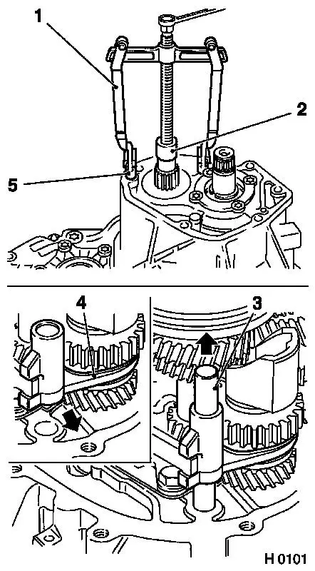
|
Remove, Disconnect Remove reverse gearshift linkage lever (1) (2 bolts).
Important! The bolts do not have a standard length. The lengths of the bolts are 20 mm/0.79 in. and 50 mm/1.20 in.
Remove, Disconnect Engage 5th gear in order to be able to reach the bolt (2) of the driver for the shift fork rod. Unscrew bolt (2) of driver of shift fork rod. Pull out shift fork rod in direction of arrow and remove driver. Notice: Note installation position of shift rod, small bore in fork for shift guide (for spring pin) faces upwards. | 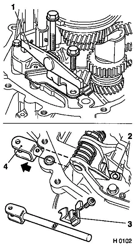
|
Remove, Disconnect Engage 4th gear, unscrew bolt (1) from shift mechanism. Raise shift mechanism slightly so that guide sleeves leave their installation position. Remove guide sleeves (2). Pull shift mechanism towards rear in direction of differential, angle slightly and remove. Lift drive shaft slightly. Lift out reverse idler shaft with reverse gear (3) (in direction of arrows). | 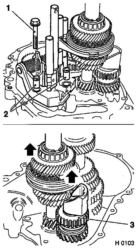
|
Remove, Disconnect Place Remover KM-859 (1) with legs under shifted 1st gear. Place Sleeve KM-857 (2) on main shaft journal. Slightly lift drive shaft with KM-859 (1). Attach Installer KM-860 (3) at the synchroniser unit of the 1st/2nd gear - secure synchroniser unit and installer with cable tie (4). Pull off all gears of the main shaft about 15 mm/0.63 in with KM-859. Remove drive shaft (5). Continue turning Remover KM-859 until gears have detached from the main shaft. | 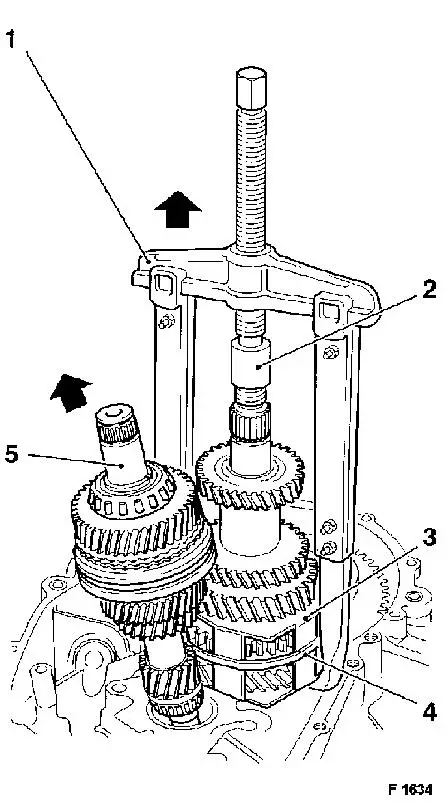
|
Remove, Disconnect Remove 4th gear (1), clamping sleeve (2), spacer sleeve (3), 3rd gear (4) and synchroniser unit of 1st/2nd gear together with KM-860 (5). Dismantle bearing support (6) of main shaft (4 bolts) - ensure correct seating of tool to prevent damaging inner torx of bolts. | 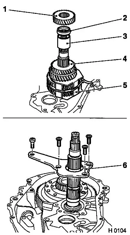
|
Remove, Disconnect Drive main shaft out of housing with KM-328-B (1) (Remover Hammer) and KM-861 (2) (Adapter).
Important! When removing main shaft, note that guide sleeves are released. Lift out differential - aligning recess in differential with protrusion on bearing support of main shaft (arrow). | 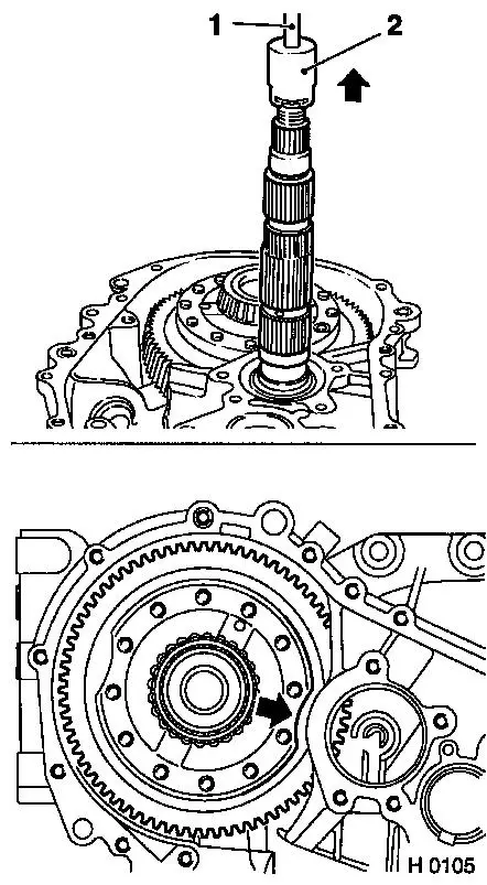
|
|
