Ring Gear - Differential, Replace (F 23) Illustration Ring gear (1)
 Remove, Disconnect Remove, Disconnect Remove transmission - see operation "Transmission, Remove and Install (F 23)".
 Disassemble Disassemble Disassemble transmission - see operation "Transmission, Seal Completely (F 23)". | 
|
Remove, Disconnect When replacing the differential ring gear, the pressure comb adjustment must be determined and adjusted if necessary. For this purpose, the tapered roller bearings must be removed from the differential - see operation "Tapered Roller Bearings - Differential, Remove and Install (F 23)".
 Measure Measure Determine dimension (I) - distance of height of ring gear to the seat of the differential tapered roller bearing on transmission casing side - using a commercially available, digital depth gauge with a measuring range of at least 250 mm and a gradation of 0.01 mm. This measurement is made at three measurement points (arrows) distributed uniformly over the ring gear and differential. The measured values are added and divided by the number of measurements. This method of calculation is illustrated clearly in the table below. | 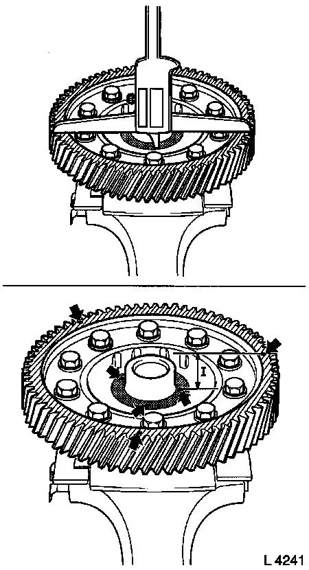
|
Notice: The purpose of the following tables is to explain the pressure comb adjustment using an example calculation.
Measure The measurement values in the left-hand table serve as a calculation example for the evaluation of the measurement; to simplify the evaluation, you can enter your measurement results in the right-hand table (on the hard copy).
|
1st measurement |
For example |
15.02 mm |
+ |
|
1st measurement |
Your values |
mm |
+ |
|
2nd measurement |
|
15.06 mm |
+ |
|
2nd measurement |
|
mm |
+ |
|
3rd measurement |
|
15.05 mm |
= |
|
3rd measurement |
|
mm |
= |
|
|
Total value |
45.13 mm |
:3= |
|
|
Total value |
mm |
:3= |
|
|
Mean value |
15,04 |
|
|
|
Mean value |
mm |
|
After installation of the new ring gear, the replacement of which is described in this operation, the measurement must be performed in the same way for the new ring gear. If, in the measurement, a value deviates from the other values by more than 0.08 mm, the measurement must be repeated because a measurement error has occurred.
Measure The mean value for the old ring gear is then subtracted from the mean value for the new ring gear. Table for example calculation of dimension difference:
|
Mean value |
New ring gear |
15.16 mm |
- |
|
Mean value |
Old ring gear |
15.04 mm |
= |
|
|
|
+ 0.12 mm |
± Difference |
Table for your dimension difference calculation:
|
Mean value |
New ring gear |
|
- |
|
Mean value |
Old ring gear |
|
= |
|
|
|
|
± Difference |
If the difference between the old and the new ring gear amounts to more than +0.02/-0.06 mm, then the pressure collar must be adjusted.
Measure If the difference is positive (+), then the shim (transmission casing side) (4) must be selected to be thicker by the same amount. If the difference is negative (-), then the shim (transmission casing side) (4) must be selected to be thinner by the same amount. If the shim (transmission casing side) (4) is thicker, the shim (clutch housing side) (1) must be selected to be thinner by the same amount. If the shim (transmission casing side) (4) is thinner, the shim (clutch housing side) (1) must be selected to be thicker by the same amount. In other words, the total thickness of the two shims remains the same. Corresponding shims can be obtained from the "Aftersales" division. The actual dimension for the shims (2) is determined using a micrometer (3) since the shims are not labelled. | 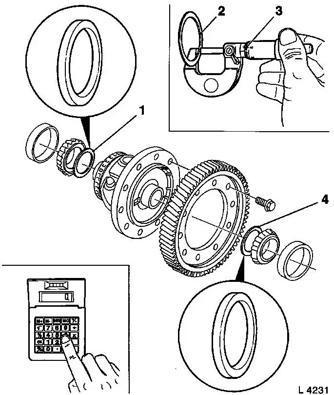
|
 Adjust Adjust A few examples for using the shims are listed in the table below.
|
Difference dimension |
Shim
(transmission casing side) |
Shim
(clutch housing side) |
|
- 0.25 mm |
Old |
|
0.90 mm |
New |
|
0.65 mm |
Old |
|
0.75 mm |
New |
|
1.00 mm |
|
+ 0.20 mm |
Old |
|
0.90 mm |
New |
|
1.10 mm |
Old |
|
0.75 mm |
New |
|
0.55 mm |
|
+ 0.13 mm |
Old |
|
0.90 mm |
New |
|
1.05 mm |
Old |
|
0.75 mm |
New |
|
0.60 mm |
|
+ 0.12 mm |
Old |
|
0.90 mm |
New |
|
1.00 mm |
Old |
|
0.75 mm |
New |
|
0.65 mm |
For the adjustment, the shims must be selected so that the smallest possible tolerance is achieved. Used shims can be re-used for subsequent adjustment operations, provided that they have not been damaged.
 Install, Connect Install, Connect Install differential tapered roller bearing - see operation "Tapered Roller Bearing - Differential, Remove and Install (F 23)".
 Inspect Inspect Check differential for damage and wear, replace if necessary.
Disassemble Clamp differential (1) in vice using jaw protectors. Remove 10 fastening bolts (arrow). Remove ring gear (2) from differential using a plastic hammer. | 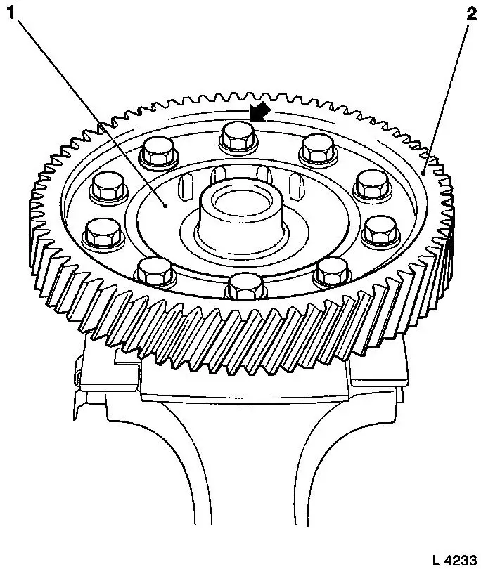
|
 Clean Clean Clean all threads (arrow) and contact surfaces (1) between ring gear and differential. | 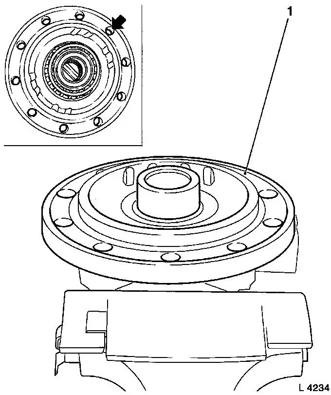
|
 Assemble Assemble Place ring gear (1) on differential (2). Insert two fastening bolts (3) and tighten slightly. Drive ring gear onto differential using a plastic hammer and tighten fully using two fastening bolts. | 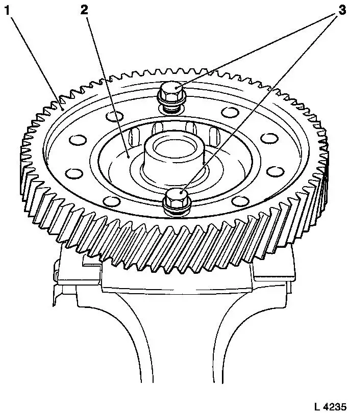
|
Install, Connect Clamp differential (1) in vice using jaw protectors. Remove the two fastening bolts previously installed. Coat new fastening bolts (arrow) with screw locking compound (red) and attach ring gear (2) to differential - tightening torque 90 Nm / 66 lbf. ft.
Assemble Assemble transmission - see operation "Transmission, Seal Completely (F 23)".
Install, Connect Install transmission - see operation "Transmission, Remove and Install (F 23)". |
|
|
