volkswagen Workshop Repair Guides

Volkswagen Workshop Service and Repair Manuals

Adjusting output shaft > < Adjusting input shaft
4 Speed Manual Gearbox 020
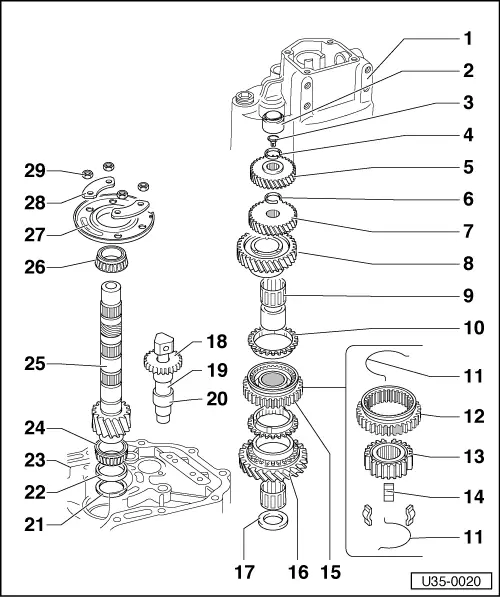
Dismantling and assembling input shaft
Dismantling and assembling output shaft
 
U35-0020

Note:

Always renew both bearings and then adjust output shaft,

When installing new gears, note Technical Data, => page 00-3

Securing the output shaft needle roller bearing, => page 35-50

  • Gearbox housing
  • Output shaft needle bearing
    • ◆ Pulling out =>Fig. 17
    • ◆ Pressing in =>Fig. 18
  • Stop for needle bearing
  • Circlip
    • ◆ Fit new, must seat properly in groove.
  • 4th speed gear
    • ◆ Replace pair only, heat to fit. Shoulder upwards.
 
U35-0020
  • Circlip
    • ◆ Fit new, must seat properly in groove =>Fig.8
  • 3rd speed gear
    • ◆ Adjust axial play =>Fig. 8 , replace pair only, heat to fit.
    • ◆ Shoulder towards 2nd speed gear.
  • 2nd speed gear
  • 2nd speed gear bearing
    • ◆ Install needle bearing inner race and knock home=>Fig. 7
  • Synchro ring for 1st and 2nd gear
    • ◆ Check for wear =>Fig.2
    • ◆ Mod. =>Fig.3
  • Spring
    • ◆ Mod.
  • Sleeve
  • Hub
 
U35-0020
  • Locking key
  • Sleeve/hub for 1st and 2nd gear
    • ◆ Remove reverse gear shaft before removing, pulling off =>Fig. 1
    • ◆ Assembling =>Fig. 4 and =>Fig.5
    • ◆ Heat to fit, drive home =>Fig. 6
    • ◆ Mod.
  • 1 st speed gear
  • thrust washer
    • Shoulder towards taper roller bearing
  • Reverse gear
    • Shoulder downwards.
  • Reverse gear shaft
    • ◆ Knock out and in with plastic hammer align =>Fig. 10
  • Bush
    • (Up to 15 06 5)
    • ◆ Mod.=> page 34-69
    • ◆ Location => Fig.9
 
U35-0020
  • Shim S3
    • ◆ See
  • Outer race, small bearing
    • ◆ Pull out =>Fig.15
    • ◆ Knock in =>Fig. 16
  • Bearing housing
  • Inner race, small bearing
    • ◆ Press off =>Fig.12 , bearing is destroyed
    • ◆ To install heat to 100°C and press home =>Fig. 13
  • Output shaft
    • ◆ Is matched to crown wheel adjust if replaced
  • Inner race, large bearing
    • ◆ Press off =>Fig.11 bearing is destroyed
    • ◆ To install, heat to 100°C and press home =>Fig.14
 
U35-0020
  • Outer race, large bearing with end cover
    • ◆ Is installed in end cover, do not press race out. Mod.
  • Reinforcement plate
    • ◆ Mod.
  • Self-locking nuts 25 Nm
    • ◆ Mod.
 
U35-0021

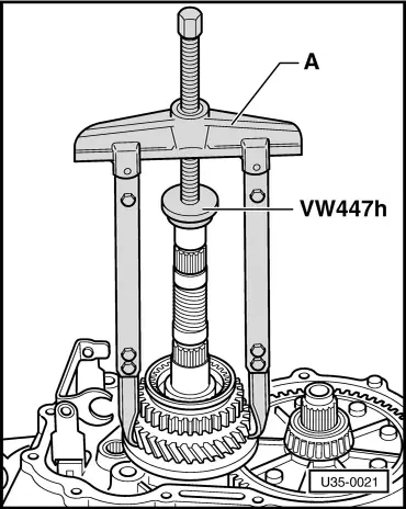
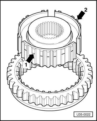
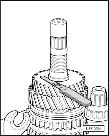
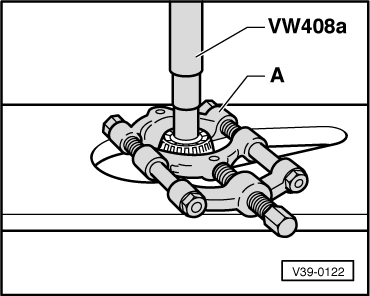
→ Fig.1     Pulling off hub/sleeve and 1st speed gear

  •      1 -     Two-arm puller such as Kukko 10-20 with 250 mm long hooks.
 
V35-0975

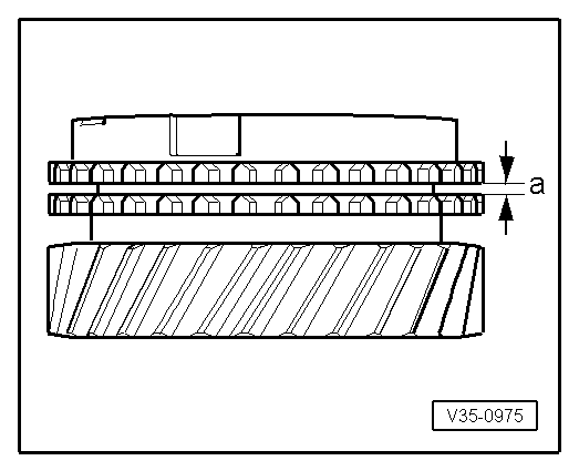
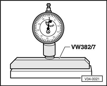
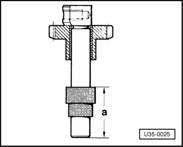
→ Fig.2     Checking synchronizer rings

Press synchro rings on to gear cones and measure gap "a" with feelers.

Gap "a"

New

Wear limit

1st and 2nd gear

1.1 -- 1.7 mm

0.5 mm

Mod:

 
V35-0465

From 20 10 6

Tooth angle on 1st gear ring changed form 120° to 110°. (2 - 4 gears still 120°).

→ Fig.3     Marking of 1st gear cynchronizer ring with 110°

Identification:

3 x 1 tooth missing -arrow- (interim period: 3 x 3 teeth)

This ring must only be installed on 1st gear.

When renewing 1st gear ring:

Use ring - Part No. 014 311 295 D - with full teeth.

 
U35-0022

→ Fig.4     Assembling hub and sleeve for 1st and 2nd gear

Fitting position for synchro hub for 1st/2nd gear

From gearbox 27 07 6

Identification groove for 1st gear side moved from splines -arrow 1- to end face -arrow 2- so that it can be seen when parts are assembled.

Position unchanged: Groove towards 1st gear.

Modification:

Locking key springs 1st - 4th gears

 
V34-0021

From gearbox 28 09 6

Wire diameter reduced from 1.6 to 1.4 mm (reduces shifting force). New springs can be installed in earlier synchromesh units.

→ Fig.5     Assembling sleeve/hub

  • ‒ Place sleeve on hub. The parts need not be fitted in a particular position.
  • ‒ Insert keys and install springs 120° offset. The angled end of the spring must engage in the hollow key.
 
U35-0023

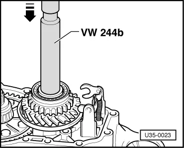
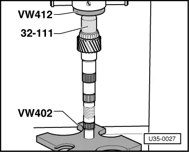
→ Fig.6     Heat the needle bearing inner race to about 120° C, place it on shaft and drive it fully home

Fitting direction:

  • ‒ Turn synchronizer rings so that grooves align with keys.
 
V34-2462

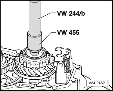
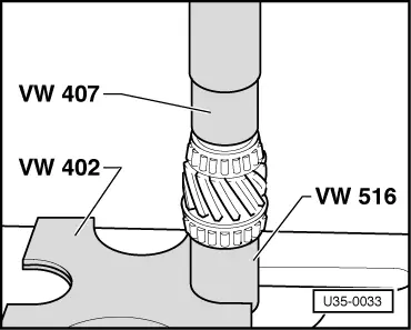
→ Fig.7     Drive needle bearing inner race fully home

 
U35-0024

→ Fig.8     Adjusting axial play of 3rd speed gear

  • ‒ Measure axial play with a feeler gauge and adjust it by selecting a suitable circlip. The play should be between 0 and 0.20 mm. Keep as near as possible to lower limit.
  • ‒ Install circlip with pliers VW 161 a.

Circlips are available in the following thickness:

Part No.

Thickness (mm)

Colour

020 311 381

2.5

brown

020 311 381 A

2.6

black

020 311 381 B

.2.7

bright

020 311 381 C

2.8

copper

020 311 381 D

2.9

brass

020 311 381 E

3.0

blue

 
U35-0025

→ Fig.9     Installing stop bush

Heat bush before installing

-a- = 41 mm

 
V35-0070

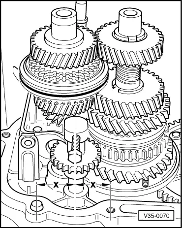
→ Fig.10     Aligning reverse gear shaft

Dimensions x should be the same.

 
U35-0026

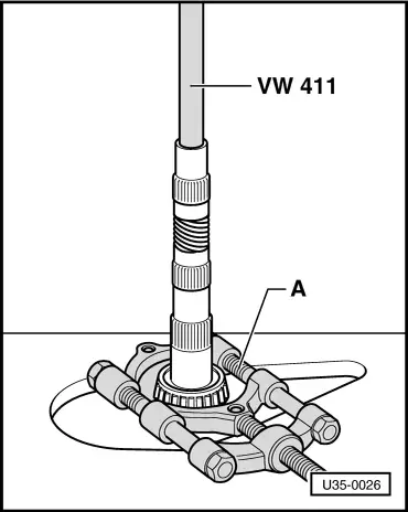
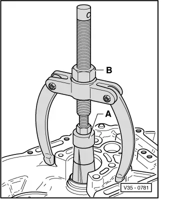
→ Fig.11     Pressing off inner race of large bearing

A - Parting appliance such as Kukko 17/2 - 22 to 115 mm.

Bearing is destroyed in the process.

 
V39-0122

→ Fig.12     Pressing off inner race of small bearing

A - Parting appliance such as Kukko 17/2 - 22 to 115 mm.

Bearing is destroyed in the process.

 
U35-0027

→ Fig.13     Heat inner race of small bearing to about 100 °C, fit on shaft and press home

 
U35-0033

→ Fig.14     Heat inner race of large bearing to about 100° C, fit on shaft and press home

 
V35-0781

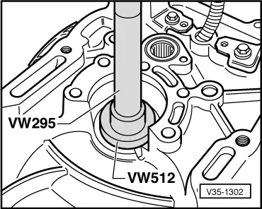
→ Fig.15     Pulling outer race of output shaft out

  •      A -     Extractor 37 - 46 mm, Kukko 21/6
  •      B -     Support from Kukko 22/2
 
V35-1302

→ Fig.16     Knocking in outer race of small bearing

 
U35-0028

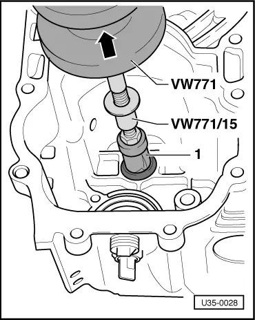
→ Fig.17     Removing output shaft needle bearing

  •      1 -     Extractor 18.5 - 23.5 mm, Kukko 21/3
 
U35-0029

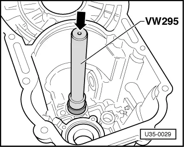
→ Fig.18     Knocking in output shaft needle bearing

Adjusting output shaft > < Adjusting input shaft