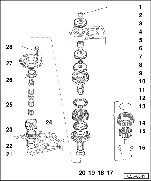
volkswagen Workshop Repair Guides

Volkswagen Workshop Service and Repair Manuals

Adjusting output shaft > < Dismantling and assembling input shaft
5 speed manual Gearbox 020
Gears, Shafts
Dismantling and assembling output shaft
 
U35-0041

Note:

  • ◆ Always renew both taper roller bearings and then adjust output shaft
  • ◆ When installing new gears, note Technical Data => page 00-4
  • ◆ Output shaft gears, removing and installing => page 34-28

Additional bearing for output shaft

Pinion shaft

  • Circlip
    • ◆ Must fit properly in groove
  • Thrust washer
  • 5th speed gear
    • ◆ Position: Groove upwards
  • Gearbox housing
  • Output shaft needle bearing
    • ◆ Pulling out =>fig. 11 .
    • ◆ Pressing in =>fig. 12 .
 
U35-0041
  • Circlip
    • Fit new, must seat properly in groove.
  • 4th speed gear
    • ◆ Replace pair only, heat to fit, shoulder upwards.
  • Circlip
    • Fit new, must seat properly in groove.
    • ◆ Find thickness => page 34-43
  • 3rd speed gear
    • ◆ Adjust axial play
    • ◆ Replace pair only, heat to fit.
    • ◆ Shoulder towards 2nd speed gear
  • 2nd speed gear
  • 2nd speed gear needle bearing
    • ◆ Lubricate with gear oil
  • Synchro ring for 2nd gear
    • ◆ Sprayed with molybdenum
      check for wear =>fig. 1 .
 
U35-0041
  • Spring
    • Wire dia. 1.4 mm
  • Sleeve
  • Hub
  • Locking key
  • Sleeve/hub for 1st and 2nd gear
    • ◆ Assembling =>fig. 3 and 4
      heat to fit
  • Synchro ring for 1st gear
    • ◆ Check for wear =>fig. 1 .
    • ◆ Identification =>fig. 2 .
  • 1st speed gear
  • Thrust washer
    • Shoulder towards taper roller bearing
 
U35-0041
  • Shim S3
  • Outer race, small bearing
    • ◆ Pull out =>fig. 9 .
    • ◆ Knock in =>fig. 10 .
  • Inner race, small bearing
    • ◆ Press off =>fig. 6 .
    • ◆ Bearing is destroyed, to install heat to 100° C and press home =>fig. 7 .
  • Bearing housing
  • Output shaft
    • Is matched to crown wheel.
    • ◆ Adjust if replaced => page 35-31
  • Inner race, large bearing
    • ◆ Press off =>fig. 5 .
    • ◆ Bearing is destroyed, to install heat to 100° C and press home =>fig. 8.
  • Bearing plate
    • ◆ With bearing outer race and reverse gear stop.
    • ◆ Do not press bearing race out.
  • 40 Nm
 
V35-0022

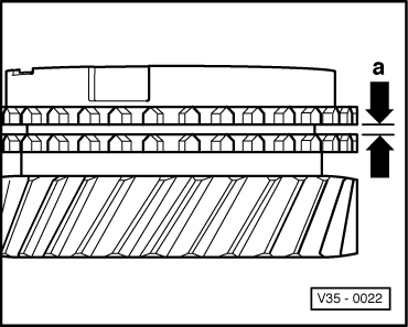
→ Fig.1     Checking synchronizer rings

Press synchro rings on to gear cones and measure gap "a" with feelers.

Gap "a"

New

Wear limit

1st and 2nd gear

1.1 - 1.7 mm

0.5 mm

 
V35-0465

→ Fig.2     Marking of 1st gear synchronizer ring with 110° tooth angle

Identification: 3 x 1 tooth missing -arrow-.

This ring must only be installed on 1st gear.

When renewing 1st gear ring:

Use ring - Part No. 014 311 295 D - with full teeth.

The 1st gear synchronizer ring with full splines - Part No. 014 311 295 D - shown as a service part in the Workshop Manual, is no longer being supplied. In case of repair the synchronizer ring show in the Parts List is to be used.

 
U35-0022

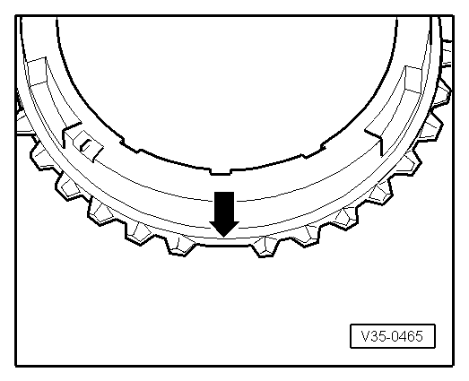
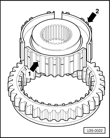
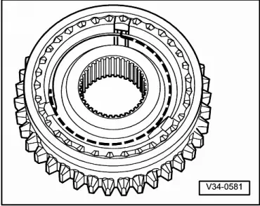
→ Fig.3     Assembling hub and sleeve for 1st and 2nd gear

Fitting position:
Identification groove on splines - arrow 1 - or end face - arrow 2 - towards 1st gear.

 
V34-0581

→ Fig.4     Assembling hub and sleeve

  • ‒ Push sleeve over hub. It is no longer necessary to fit parts in a
    particular position.
  • ‒ Insert keys and install springs 120° offset. The spring with the angled end must engage in the hollow key.
 
V35-0779

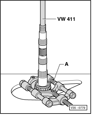
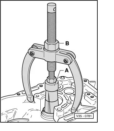
→ Fig.5     Pressing off inner race of large bearing

A - Parting appliance such as kukko 17/2 - 22 to 115 mm.

Bearing is destroyed in the process.

 
V39-0122

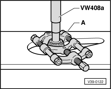
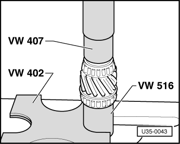
→ Fig.6     Pressing off inner race of small bearing

A - Parting appliance such as kukko 17/2 - 22 to 115 mm.

Bearing is destroyed in the process.

 
U35-0042

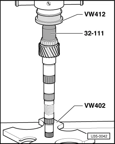
→ Fig.7     Heat inner race of small bearing to about 100° C, fit on shaft and press home

 
U35-0043

→ Fig.8     Heat inner race of large bearing to about 100° C, fit on shaft and press home

 
V35-0781

→ Fig.9     Pulling outer race of small bearing out of bearing housing

  •      A -     Extractor 37 - 46 mm, Kukko 21/6
  •      B -     Support from Kukko 22/2
 
V35-1302

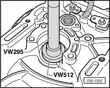
→ Fig.10     Knocking outer race of small bearing into bearing

housing

 
V34-2567

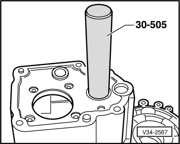
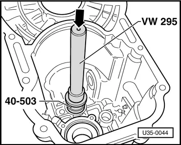
→ Fig.11     Knocking needle bearing out of gearbox housing

 
U35-0044

→ Fig.12     Knocking needle bearing into gearbox housing

Adjusting output shaft > < Dismantling and assembling input shaft