volkswagen Workshop Repair Guides

Volkswagen Golf Workshop Service and Repair Manuals

Dismantling and assembling output shaft > < Gears, Shafts
5 speed manual Gearbox 020
Gears, Shafts
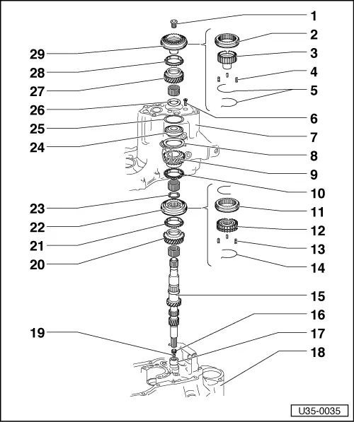
Dismantling and assembling input shaft

Synchronizer hub for 5th gear with retaining ring for locking keys =>page 35-36

Note:

When installing new gears, see Technical Data

  • M 17 screw 150 Nm
    • ◆ Renew, coat new screw with D 6 locking solution
  • Sleeve
  • Hub
  • Locking key
    • Long side towards synchro ring
  • Spring
    • Wire dia. 1.4 mm.
  • M 7 x 24 screw - 15 Nm
  • Gearbox housing
  • Clamping plate
    • ◆ Secures bearing =>fig. 9 .
 
U35-0035
  • 4th speed gear
  • Synchro ring for 4th gear
    • ◆ Check for wear =>fig. 3 .
  • Sleeve
  • Hub
  • Locking key
  • Spring
    • Wire dia. 1.4 mm
  • Input shaft
  • Bush for clutch push rod
    • ◆ Position =>fig. 10 .
    • ◆ Knocking out =>fig. 12 .
    • ◆ Knocking in =>fig. 13 .
  • Needle bearing for input shaft
    • ◆ Pulling out =>fig. 16 .
    • ◆ Knocking in =>fig. 17 .
  • Bearing housing
 
U35-0035
  • Seal for clutch push rod
    • Can be replaced with gearbox out (not dismantled)
    • ◆ Position =>fig. 10 .
    • ◆ Knocking out =>fig. 11 .
    • ◆ Pressing In =>fig. 14 .
  • 3rd speed gear
  • Synchronizing for 3rd gear
    • ◆ Sprayed with molybdenum check for wear =>fig. 3 .
  • Sleeve/hub for 3rd / 4th gear
    • ◆ Pressing off =>fig.2
    • ◆ Pressing off =>figs.4 - 6 .
    • ◆ Pressing on =>fig.7 .
  • Circlip
    • Fit new, do not over stretch, must seat properly in groove.
 
U35-0035
  • Ball bearing
    • ◆ Pressing off =>fig.1 .
    • ◆ Pressing into gearbox housing
      =>fig.8 .
    • Up to assembly date 31 05 9:
    • When renewed, use 020 311 123 G
    • ◆ Press inner race off and on separately =>fig.18 and 19 .
  • Shim for input shaft
  • Thrust washer
    • ◆ Position: Chamfer on outer dia.
      towards ball bearing
  • 5th speed gear
  • Synchro ring for 5th gear
    • ◆ Check for wear => fig. 3 .
  • Sleeve/hub for 5th gear
    • ◆ Assembling => fig. 15 .
 
U35-0036

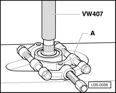
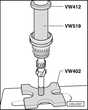
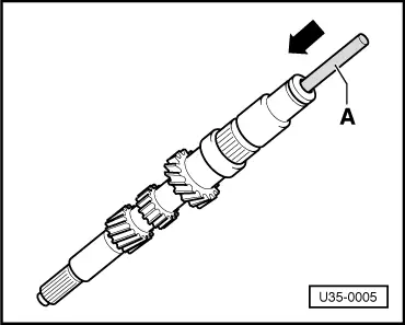
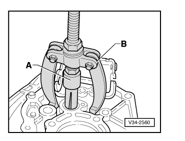
→ Fig.1     Pressing ball bearing off

A - Separating appliance 12 - 75 mm - e.g. Kukko 17/1.

 
N35-0176

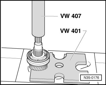
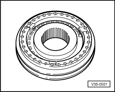
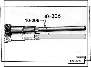
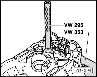
→ Fig.2     Pressing off sleeve/hub with 3rd speed gear

 
V35-0975

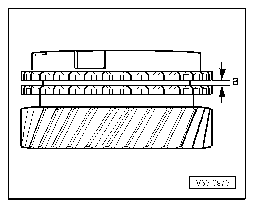
→ Fig.3     Checking synchronizer rings

Press synchro ring on to gear cone and measure gap "a" with feelers

Gap "a"

New

wear limit

3rd speed

1.15-1.75 mm

0.5 mm

4th+5th speed

1.3-1.9 mm

0.5 mm

 
U35-0009

→ Fig.4     Assembling sleeve and hub for 3rd/4th gear

Position:

The chamfer on the inner splines of the hub - arrow 1 - goes towards 3rd gear.

Additional identification groove - arrow 2 - goes towards 4th gear.

 
34-2047

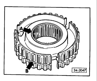
→ Fig.5     Identification of hub for 3rd/4th gear

Either a groove -withe arrow- on hub (4th gear side) or axial grooves or the splines -black arrow-.

 
V35-0021

→ Fig.6     Assembling sleeve/hub for 3rd/4th gear

  • ‒ Push sleeve over hub. It is no longer necessary to assemble the parts in a particular position.
  • ‒ Install keys and fit springs 120° offset. The spring with the angled end must engage in the hollow key.
 
U35-0037

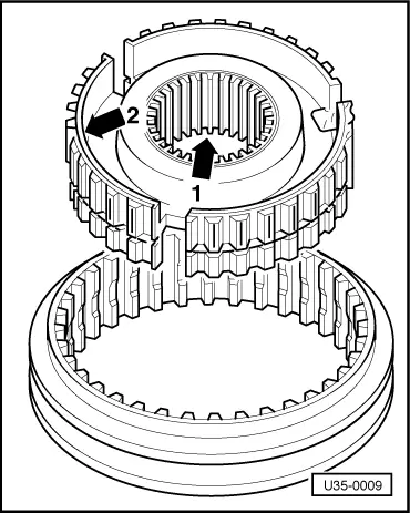
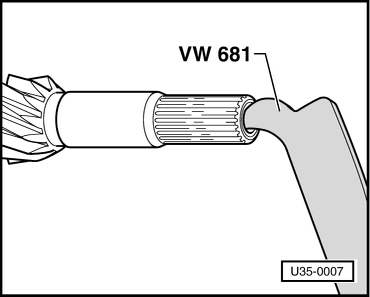
→ Fig.7     Pressing hub and sleeve on

Fitting direction:
See =>fig. 4 .

Turn synchronizer ring so that grooves align with keys.

 
V35-1274

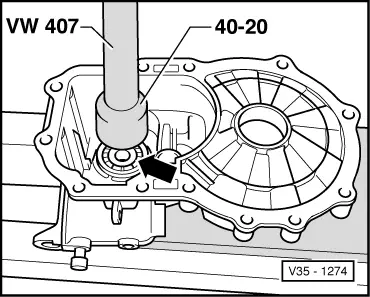
→ Fig.8     Pressing ball bearing and shim into the gearbox housing

Fitting direction:
Wide shoulder on inner race towards 4th gear.

Secure with clamping plate =>fig. 9 .

 
V35-0772

→ Fig.9     Securing clamping plate

 
V35-0670

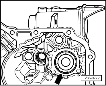
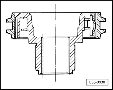
→ Fig.10     Position of seal and bush

  •      A -     Seal for clutch push rod
  •      B -     Bush for clutch push rod
 
U35-0007

→ Fig.11     Pulling seal for clutch push rod out

Can be removed with gearbox out without dismantling box

 
U35-0005

→ Fig.12     Knocking out bush for clutch push rod

A = 10 mm rod such as an old pump shaft from automatic gearbox.

 
U35-0008

→ Fig.13     Drive bush in fully

 
V34-0790

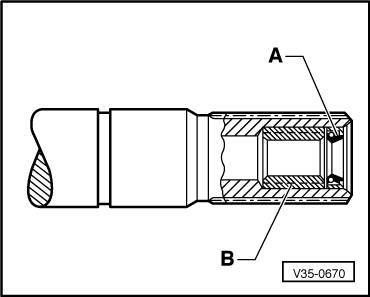
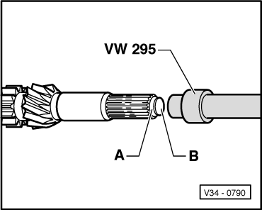
→ Fig.14     Installing seal

Push seal -A- in with the fitting plug -B- supplied. Take plug out. The seal is then in the correct position. (0.8 - 1.3 mm deep). Oil lips of seal.

 
U35-0038

→ Fig.15     Assembling hub and sleeve for 5th gear

  • ‒ Push sleeve over hub. It is not necessary to assemble the parts in a particular position.
  • ‒ Insert keys with long side downwards (towards synchronizer ring).
  • ‒ Install both springs from below 120° offset.
  • ‒ The spring with the angled end must engage in the hollow key.
 
V34-2560

→ Fig.16     Pulling needle bearing out of bearing housing

  •      A -     Extractor 18.5-23.5 mm e.g. Kukko 21/3
  •      B -     Support e.g. Kukko 22/2
 
V34-2476

→ Fig.17     Knocking needle bearing into bearing housing

 
U35-0039

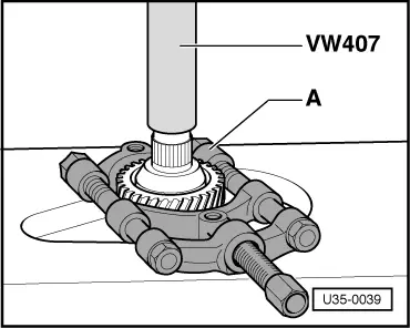
→ Fig.18     Pressing off 4th speed gear and ball bearing inner racer

  •      A -     Separating tool, 12 - 75 mm e.g. Kukko 17/1.

Only up to assembly date 31 059

 
U35-0040

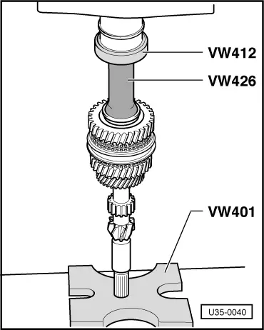
→ Fig.19     Pressing on ball bearing inner race

Only up to assembly date 31 05 9.

Dismantling and assembling output shaft > < Gears, Shafts