volkswagen Workshop Repair Guides

Volkswagen Golf Mk1 Workshop Service and Repair Manuals

Checking knock sensor > < Checking ignition timing
Motronic MP 9.0 injection and ignition system
Motronic injection and ignition system
Checking Hall sender

Special tools, testers and auxiliary items

  • ◆ Test box V.A.G 1598/18
  • ◆ Hand multimeter V.A.G 1526 or multimeter V.A.G 1715
  • ◆ Adapter set V.A.G 1594
  • ◆ Current flow diagram

Test conditions

  • ● Sender fault is recognised by self diagnosis

Test sequence

 
V28-0394
  • ‒ Pull plug off sender (distributor).
  • ‒ → Connect multimeter to measure voltage with aux. cables from V.A.G 1594 to the outer contacts of the plug.
  • ‒ Switch on ignition.
         Specification: At least 10 V
  • ‒ Switch off ignition.
 
N24-0165
  • ‒ → Connect test box V.A.G 1598/18 to control unit wiring loom.
 
N28-0016
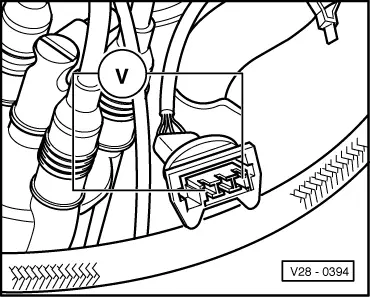
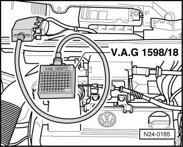
  • ‒ → Check wiring between test box and 3 pin connector to open circuit according to current flow diagram.
         Contact 3 + socket 8
         Contact 2 + socket 13
         Contact 1 + socket 17
         Wire resistance: 1.5 ω
  • ‒ Additionally check wires for short to one another.
         Contact 1 + socket 13
         Contact 1 + socket 8
         Contact 2 + socket 8
         Specification:∞ω

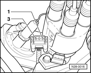
If no wiring fault is detected and voltage was present between contacts 1 + 3.

  • ‒ Renew distributor with Hall sender , item 17 .

If no wiring fault is detected and no voltage was present between contacts 1 + 3.

  • ‒ Replace Motronic control unit (J220) => Page 24-5 , item 3

Checking knock sensor > < Checking ignition timing