volkswagen Workshop Repair Guides

Volkswagen Workshop Service and Repair Manuals

Dismantling and assembling shift mechanism (vehicles with ignition key removal lock) > < Checking ignition key removal lock (vehicles with ignition key removal lock)
Automatic gearbox 096
Servicing shift mechanism
Dismantling and assembling shift mechanism
 
N37-0080
  • Selector lever handle
  • Set screw, 1.5 Nm
  • Cover
    • ◆ With selector indicator
    • ◆ With hole for vehicles with programme switch on selector lever => Item 32
  • Protective sleeve for selector lever
  • Cover strip
    • ◆ Insert into cover -Fig. 3-
 
N37-0080
  • Selector lever lock solenoid -N110-
    • ◆ Can be equipped with a single or two part wiring loom
    • ◆ Securing wiring loom to selector housing (selector lever lock solenoid with single wiring loom) => Fig. 7
    • ◆ Securing indicator lighting connector => Fig. 8
    • ◆ Securing selector lever lock solenoid and scale lighting wiring loom
      => Fig. 9
    • ◆ Functional check => Fig. 5
    • ◆ Adjusting => Fig. 10
    • ◆ Can be checked electrically
  • Bolt, 3 Nm
    • ◆ Qty. 2
    • ◆ Install with locking fluid AMV 185 101 A1
 
N37-0080
  • Combi-bolt
    • ◆ Grease shank
  • Bush
  • Locking washer
    • ◆ Installing => Fig. 6
  • Selector lever
    • ◆ To remove selector lever, lower protective plate is removed and front protective plate removed and pushed forward.
    • ◆ Assemble before installing
      => Fig. 3
 
N37-0080
  • Indicator lighting
    • ◆ On right-hand drive vehicles there is an additional contact which prevents starting the engine when the "selector lever handle" locking button has been pressed
    • ◆ Securing indicator lighting connector (solenoid with single wiring loom) => Fig. 8
    • ◆ Securing selector lever lock solenoid and indicator lighting wiring loom (wiring loom not an integral part of solenoid) => Fig. 9
  • Spring
    • ◆ Insert together with lever -Fig. 14- into selector lever
  • Lever
    • ◆ To lock in selector lever position "P" or "N"
  • Bush
  • Nut, 10 Nm
    • ◆ Always renew
 
N37-0080
  • Gasket
  • Selector lever housing
    • ◆ Need not be removed to replace selector lever cable or individual parts of shift mechanism
    • ◆ Securing selector lever housing => Fig. 1
    • ◆ Removing => Fig. 2
  • Combi-bolt, 25 Nm
    • ◆ Qty. 2/4 => Fig. 1
  • Nut, 15 Nm
    • ◆ Qty. 3
    • ◆ Always renew
  • Hexagon nut, 25 Nm
    • ◆ With shoulder
    • ◆ Installing => Fig. 1
  • Distance piece
  • Nuts
    • ◆ To secure central console
 
N37-0080
  • Protective sleeve
    • ◆ Insert into selector lever housing before attaching selector lever cable =>Fig. 1
  • Selector lever cable
    • ◆ To remove selector lever, lower protective plate is removed, exhaust system is separated in front of catalyst (catalyst is removed on 6-Cyl. engines) and front protective plate removed
    • ◆ Do not bend or kink , lightly grease cable eyelet and cable ends before installing
    • ◆ Tighten selector lever cable on anchorage/selector lever housing to 20 Nm
    • ◆ Check guide tube for tight fit
    • ◆ Check that protective sleeve between console and lever/selector shaft is correctly located and secure selector lever cable with corrugated locking element
    • ◆ Securing selector lever cable to selector lever => Fig. 6
    • ◆ Adjusting => Page 37-4
 
N37-0080
  • Gearbox
  • Lever
    • ◆ For selector shaft
  • Console
    • ◆ With anchorage for selector lever cable
  • Washer
  • Combi-bolt, 25 Nm
  • Corrugated locking element
    • ◆ For selector lever cable
    • ◆ Always renew
  • Programme switch -E122-
    • ◆ Only on vehicles with programme switch -E122-
      => Page 00-3
    • ◆ Discontinued from 01.93 => Gearboxes for vehicles with electronic programme switch, Page 00-5
    • ◆ Can be checked electrically => Page 01-46
 
N37-0081

→ Fig.1    Securing the selector housing

  • ‒ Before installing the selector lever cable insert boot (arrow).

Note:

When securing the selector housing with 4 bolts -A-, the nut with collar -B- is no longer fitted.

 
N37-0143

→ Fig.2    Removing selector lever housing

  • ‒ Remove rear centre console.
  • ‒ Remove hexagon nut with shoulder.
  • ‒ Remove lower protective plate.
  • ‒ Disconnect Lambda probe connector, separate exhaust system in front of catalyst (remove catalyst on vehicles with 6-Cyl. engine).
  • ‒ Remove front protective plate and rear lower bolts (arrows).
 
N37-0068

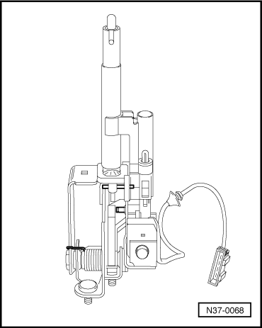
→ Fig.3    Assembling selector lever before installing

Adjust solenoid => Fig. 10 for selector lever lock -N110- and carry out functional check => Fig. 5 before installing selector lever in selector lever housing.

  • ‒ Install set screw and selector lever lock solenoid -N110- screw with locking fluid AMV 185 101 A1.
 
N37-0083

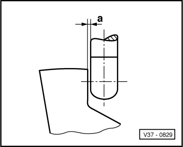
→ Fig.4    Adjusting selector lever lock solenoid -N110-

  • ‒ Adjust solenoid by sliding in elongated holes so that a clearance -a- of 0.3 mm exists between pressure rod and lever => Fig. 5.
 
V37-0829

→ Fig.5    Adjusting clearance between pressure rod and lever

Dimension a = 0.3 mm

Functional check

  •     1 -    Shift selector lever into "P" and supply solenoid with 12 V. It must not be possible to shift lever into a driving gear.
  •      -    Interrupt solenoid operation; it must be possible to shift into all driving gears.
  •      -    Pressure rod must not catch on lever.
 
N37-0070
  •     2 -    Shift selector lever into "N" and check as in 1.
  •      -    After adjusting clearance, install assembled selector lever.

→ Fig.6    Attaching selector lever cable to selector lever

  • ‒ Fit selector lever cable eye (arrow) on selector lever and secure with circlip.
 
N37-0067

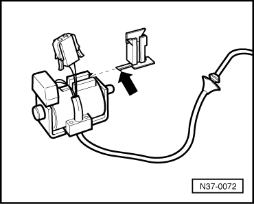
→ Fig.7    Securing wiring loom to selector lever housing

(Solenoid with single wiring loom)

  • ‒ Press wiring loom into clips and into selector lever housing (arrows).
 
N37-0072

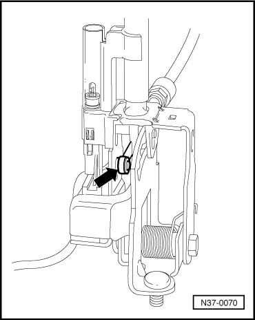
→ Fig.8    Securing indicator lighting connector

  • ‒ Push bracket with lug (arrow) on until lug engages.
  • ‒ Seat connector cable into bracket and slide connector onto bracket.
 
N37-0082

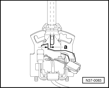
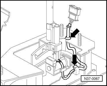
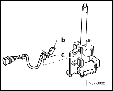
→ Fig.9    Securing selector lever lock solenoid "a" and scale lighting "b" wiring loom

(Wiring loom not an integral part of solenoid)

Dismantling and assembling shift mechanism (vehicles with ignition key removal lock) > < Checking ignition key removal lock (vehicles with ignition key removal lock)