volkswagen Workshop Repair Guides

Volkswagen Workshop Service and Repair Manuals

Dismantling and assembling selector lever (vehicles with ignition key removal lock) > < Dismantling and assembling shift mechanism
Automatic gearbox 096
Servicing shift mechanism
Dismantling and assembling shift mechanism (vehicles with ignition key removal lock)
 
N37-0084
  • Ignition/starter switch
  • Locking cable
    • ◆ Must not be kinked
    • ◆ Adjusting
    • ◆ Removing and installing => Page 37-35
  • Clip
    • ◆ For securing locking cable
    • ◆ Always renew
  • Selector lever handle
  • Set screw, 1.5 Nm
  • Cover
    • ◆ With selector indicator
    • ◆ With hole for vehicles with programme switch on selector lever => Item 29
 
N37-0084
  • Protective sleeve for selector lever
  • Cover strip
    • ◆ Insert in cover -Fig. 6-
  • Selector lever
    • ◆ Dismantling and assembling => Page 37-27
    • ◆ To remove selector lever, lower protective plate is removed and front protective plate removed and pushed forward.
    • ◆ When installing selector lever, insert locking cable anchorage in notch of selector lever housing.
    • ◆ Securing wiring loom to selector lever housing (selector lever lock solenoid with single wiring loom) => Fig. 3
    • ◆ Securing wiring loom for selector lever lock solenoid and scale lighting (wiring loom not an integral part of solenoid) => Fig. 5
 
N37-0084
  • Nuts
    • ◆ To secure central console
  • Distance piece
  • Gasket
  • Selector lever housing
    • ◆ Need not be removed to renew selector lever cable or individual parts of shift mechanism
    • ◆ Securing selector lever housing => Fig. 1
    • ◆ Removing => Fig. 2
  • Screw, 25 Nm
    • ◆ Qty. 2 / 4 => Fig. 1
  • Nut, 15 Nm
    • ◆ Always renew
    • ◆ Qty. 3
 
N37-0084
  • Protective sleeve
    • ◆ Insert into selector lever housing before attaching selector lever cable =>Fig. 1
  • Hexagon nut, 25 Nm
    • ◆ With shoulder
    • ◆ Installing => Fig. 1
  • Selector lever cable
    • ◆ To remove selector lever, lower protective plate is removed, exhaust system is separated in front of catalyst (catalyst is removed on 6-Cyl. engines) and front protective plate removed.
    • ◆ Do not bend or kink, lightly grease cable eye and cable ends before installing.
    • ◆ Tighten selector lever cable on cable anchorage/selector lever housing to 20 Nm
 
N37-0084
    • ◆ Check guide tube for tight fit
    • ◆ Check protective sleeve between console and lever/gearshift shaft for proper seating and secure selector lever cable with corrugated locking element
    • ◆ Attach selector lever cable to selector lever => Fig. 6
    • ◆ Adjusting => Page 37-4
  • Seal
    • ◆ Bonded to cable anchorage
    • ◆ Renew if damaged
  • Circlip
    • ◆ Install after fitting selector lever cable => Fig. 6
  • Washer
  • Bolt, 6 Nm
    • ◆ Loosen to adjust locking cable => Page 37-40
 
N37-0084
  • Gearbox
  • Lever
    • ◆ For selector shaft
  • Console
    • ◆ With cable anchorage for selector lever cable
  • Washer
  • Combi-bolt, 25 Nm
  • Corrugated locking element
    • ◆ For selector lever cable
    • ◆ Always renew
  • Programme switch -E122-
    • ◆ Only for vehicles with programme switch -E122-
      => Page 00-3
    • ◆ Discontinued from 01.93 => Gearboxes for vehicles with electronic programme switch, Page 00-5
    • ◆ Can be checked electrically => Page 01-46
 
N37-0081

→ Fig.1    Securing selector lever housing

  • ‒ Before attaching selector lever cable insert boot (arrow).

Note:

When securing the selector lever housing with 4 bolts -A-, the nut with collar -B- is not fitted.

 
N37-0143

→ Fig.2    Removing selector lever housing

  • ‒ Remove rear central console.
  • ‒ Remove hexagon nut with shoulder.
  • ‒ Remove lower protective plate.
  • ‒ Disconnect Lambda probe connector, separate exhaust system in front of catalyst (remove catalyst on vehicles with 6-Cyl. engine).
  • ‒ Remove front protective plate and rear lower bolts (arrows).
 
N37-0067

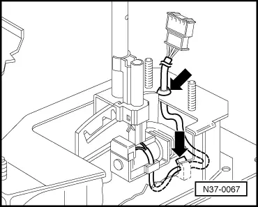
→ Fig.3    Securing wiring loom to selector lever housing

(Solenoid with single wiring loom)

  • ‒ Press wiring loom into clips and into selector lever housing (arrows).
 
N37-0073

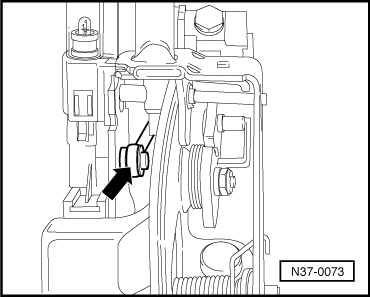
→ Fig.4    Attaching selector lever cable to selector lever

  • ‒ Fit selector lever cable eye (arrow) on selector lever and secure with circlip.
 
N37-0082

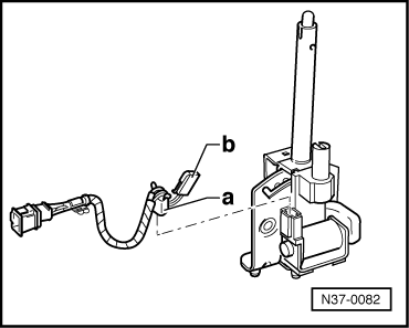
→ Fig.5    Securing selector lever lock solenoid "a" and scale lighting "b" wiring loom

(Wiring loom not an integral part of solenoid)

Dismantling and assembling selector lever (vehicles with ignition key removal lock) > < Dismantling and assembling shift mechanism