volkswagen Workshop Repair Guides

Volkswagen Workshop Service and Repair Manuals

Removing and installing locking cable (vehicles with ignition key removal lock) > < Dismantling and assembling shift mechanism (vehicles with ignition key removal lock)
Automatic gearbox 096
Servicing shift mechanism
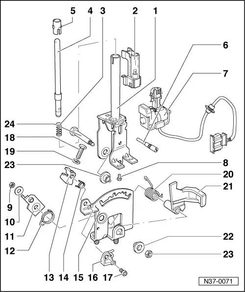
Dismantling and assembling selector lever (vehicles with ignition key removal lock)
 
N37-0071

Note:

Selector lever must be removed to renew individual parts

.

  • Selector lever
    • ◆ Assembling => Fig. 1
  • Indicator lighting
    • ◆ Securing indicator lighting connector (solenoid with single wiring loom) => Fig. 4
    • ◆ On right-hand drive vehicles there is an additional contact which prevents the engine being started when the locking button on "selector lever handle" is pressed in
 
N37-0071
  • Spring
  • Push rod
    • ◆ Grease in area of sliding surfaces
  • Guide sleeve
    • ◆ Fit after installing pressure rod
  • Set screw
    • ◆ Always renew
    • ◆ To remove set screw, remove solenoid for selector lever lock and scale lighting. Clamp set screw in vice and loosen by turning selector lever.
    • ◆ Install with locking fluid AMV 185 101 A1
 
N37-0071
  • Selector lever lock solenoid -N110-
    • ◆ Can have a single or two part wiring loom
    • ◆ Adjusting =>Fig. 2
    • ◆ Functional check => Fig. 3
    • ◆ Securing wiring loom to selector lever housing (selector lever lock solenoid with single wiring loom) , Fig. 3
    • ◆ Securing selector lever solenoid and indicator lighting wiring loom => Page 37-26, Fig. 5
    • ◆ Securing indicator lighting connector => Fig. 4
    • ◆ Can be checked electrically => Page 01-46
 
N37-0071
  • Screw, 3 Nm
    • ◆ Qty. 2
    • ◆ Install with locking fluid AMV 185 101 A1
  • Nut, 5 Nm
    • ◆ Always renew
  • Washer
  • Locking lever
    • ◆ For ignition key removal lock
    • ◆ Adjust together with locking cable
  • Spring
    • ◆ Hook into hole of detent plate
  • Retainer
    • ◆ For locking cable
    • ◆ Removing and installing locking cable => Page 37-35
    • ◆ Adjusting locking cable => Page 37-40
 
N37-0071
  • Spring
    • ◆ For locking pin
  • Detent plate
    • ◆ Assemble selector lever before fitting in selector lever housing => Fig.1
  • Locking pin
    • ◆ With bracket
  • Hexagon socket headed screw,
    6 Nm
  • Screw, 6 Nm
  • Washer
  • Spring
    • ◆ Insert in selector lever together with lever -Item 21-
 
N37-0071
  • Lever
    • ◆ For locking in selector lever position "N" or "P"
    • ◆ Adjusting =>Fig. 2
  • Bush
  • Nut, 10 Nm
    • ◆ Always renew
  • Combi-bolt
    • ◆ Grease shank
 
N37-0074

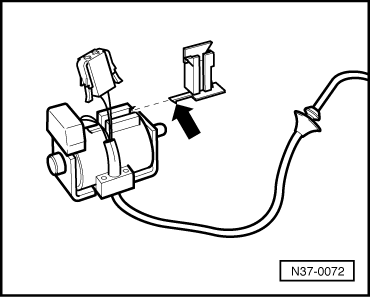
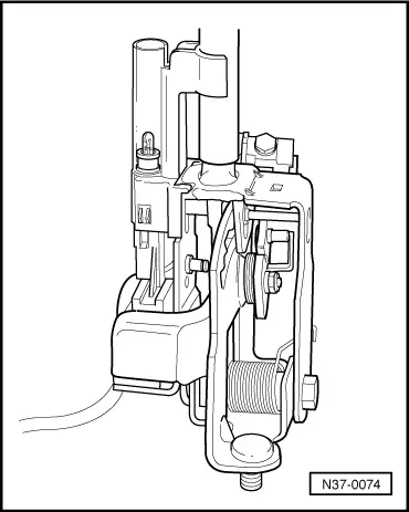
→ Fig.1    Assembling selector lever before installing

Adjust solenoid for selector lever lock -N110- => Fig. 2 and carry out functional check => Fig. 3 before installing selector lever in selector lever housing.

  • ‒ Install set screw and selector lever lock solenoid -N110- screw with locking fluid AMV 185 101 A1.
 
N37-0075

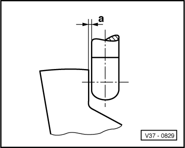
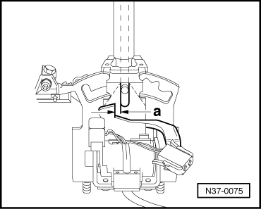
→ Fig.2    Adjusting selector lever lock solenoid -N110-

  • ‒ Adjust solenoid by sliding in elongated holes so that a clearance -a- of 0,3 mm exists between pressure rod and lever => Fig. 3.
 
V37-0829

→ Fig.3    Adjusting clearance between pressure rod and lever

Dimension a = 0.3 mm

Functional check

  • ‒ Shift selector lever into "P" and supply solenoid with 12 V. It must not be possible to shift selector lever into a driving gear
    • ‒ Interrupt solenoid operation; it must be possible to shift into driving gears.
  • Pressure rod must not catch on lever.
  • ‒ Shift selector lever into "N" and check as in "P".
 
N37-0072
  • ‒ After adjusting clearance, install assembled selector lever.

→ Fig.4    Securing indicator lighting connector

(Solenoid with single wiring loom)

  • ‒ Push bracket with lug (arrow) on until lug engages.
  • ‒ Seat connector cable into bracket and slide connector onto bracket.

Removing and installing locking cable (vehicles with ignition key removal lock) > < Dismantling and assembling shift mechanism (vehicles with ignition key removal lock)