|
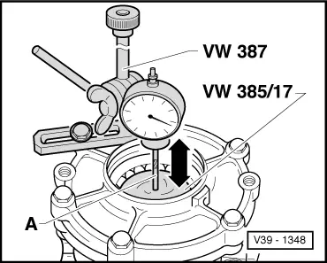
Pinion housing with shaft bevel gear and S3 installed
Bevel gear with input shaft with Stotalfitted to S2side (Example: 1.85 mm) installed. Friction torque for bevel gear with input shaft and shaft bevel gear bearings must be correct.
-
‒ →
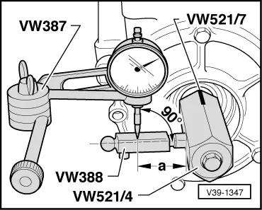
Fit measuring tools.
-
‒ Gauge extension approx. 25 mm long
-
‒ Dimension "a" = 39 mm
-
‒ Install measuring lever VW 388 so that the gauge extension is at right angles to measuring face.
-
‒ Turn bevel gear with input shaft in onto stop. Zero dial gauge, turn bevel gear with input shaft back and read off backlash. Note value.
-
‒ Loosen clamping sleeve locking screw and after turning bevel gear with input shaft through a further 90°, repeat complete measuring process a further 3 times. Add the four measured values together and calculate average backlash.
Calculating average backlash
Example:
|
|
1st measurement
|
1.25 mm
|
|
|
+
|
2nd measurement
|
1.24 mm
|
|
|
+
|
3rd measurement
|
1.25 mm
|
|
|
+
|
4th measurement
|
1.26 mm
|
|
|
Total
|
5.00 mm
|
|
|
|
|
|
|
Average backlash = 5.00 mm /4
= 1.25 mm.
Note:
The relationship backlash to bevel gear with input shaft displacement is almost a ratio of 1:1. Therefore the calculated average backlash can be used directly for calculating S2.
Determining shim S2 thickness
|
S2
|
=
|
Inserted shim (Stotal)
|
|
|
-
|
average backlash
|
|
|
+
|
Lift (constant)
|
Lift = 0.20 mm
|
Example:
|
|
|
|
Fitted shim
|
1.85 mm
|
|
-
|
average backlash
|
1.25 mm
|
|
|
|
0.60 mm
|
|
+
|
Lift (constant)
|
0.20 mm
|
|
S2
|
=
|
0.80 mm
|
The following adjustment shims are available:
|
|
|---|
|
Size (mm)
|
Part No.
|
|
0.15
0.20
0.30
|
113 517 201A
113 517 202A
113 517 203A
|
|
0.40
0.50
0.60
|
113 517 204A
113 517 205A
113 517 206A
|
|
0.70
0.80
0.90
|
113 517 207A
113 517 208A
113 517 209A
|
|
1.00
1.20
|
113 517 210A
113 517 211A
|
-
‒ Install determined shim S2 instead of Stotal.
If the size of shim required is larger than those listed in the table, insert two shims totalling the correct figure.
-
‒ Different tolerances make it possible to select the exact thickness of shim(s) required.
-
‒ Press outer race in again and fit bevel gear with input shaft.
Determining shim S1thickness
|
S1
|
=
|
Stotal - S2
|
|
|
Example:
|
|
|
S1
|
=
|
1.85 mm - 0.80 mm
|
|
S1
|
=
|
1.05 mm
|
|
|
|
|
|
|
The following adjustment shims are available:
|
|
|---|
|
Size (mm)
|
Part No.
|
|
0.70
0.75
0.80
0.85
0.90
0.95
1.00
1.05
1.10
1.15
1.20
1.25
1.30
1.35
|
02C 409 247
02C 409 247A
02C 409 247B
02C 409 247C
02C 409 247D
02C 409 247E
02C 409 247F
02C 409 247G
02C 409 247H
02C 409 247J
02C 409 247K
02C 409 247L
02C 409 247M
02C 409 247N
|
-
‒ Insert determined S1 shim.
If the size of shim required is larger than those listed in the table, insert two shims totalling the correct figure.
-
‒ Different tolerances make it possible to determine the exact thickness of shim(s) required.
-
‒ Press outer race in again.
-
‒ Fit cover.
Carry out control measurement - measuring backlash
-
‒ It must be 0.15...0.25 mm.
|