
Golf Mk3
|
Removing and installing gearbox
Removing and installing gearbox
|
 |
|
|
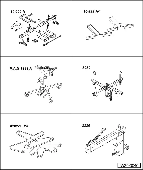
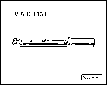
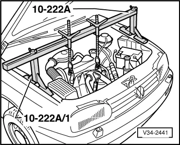
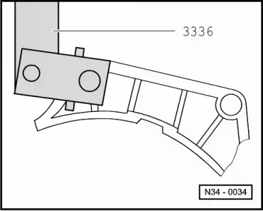
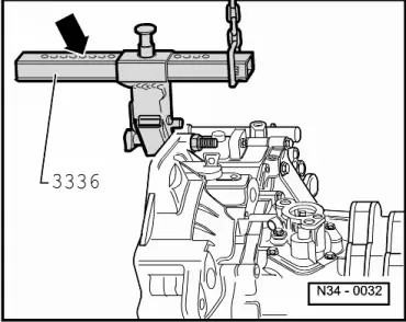
Special tools and workshop equipment required
Removing |
 |
|
Note: Check whether a coded radio is installed as during the forthcoming work sequences the battery earth strap must be disconnected. Obtain radio code first if necessary.
=> Repair group 21; Removing and installing parts of turbocharger |
 |
|
|
 |
|
|
 |
|
|
 |
|
Note: Do not depress clutch pedal.
|
 |
|
|
 |
|
Note: Do not open cooling system. |
 |
|
|
 |
|
|
 |
|
|
 |
|
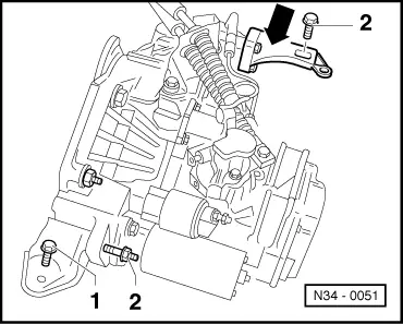
=> Repair group 27; Removing and installing starter.
=> Repair group 26; Removing and installing parts of exhaust system.
|
 |
|
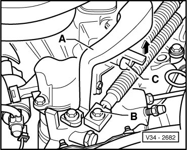
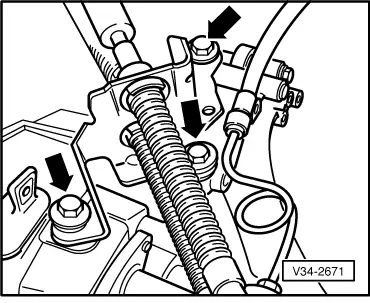
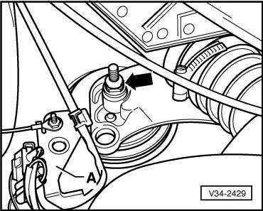
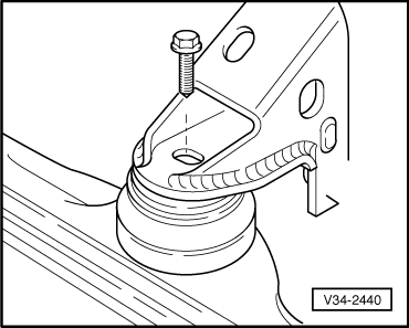
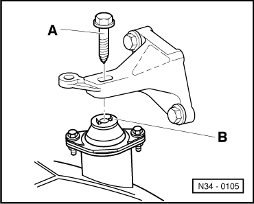
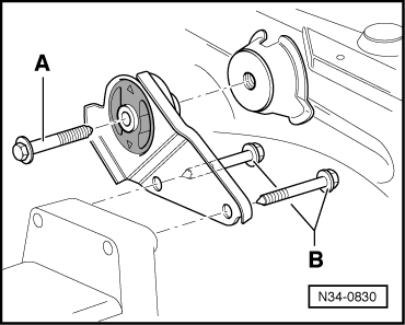
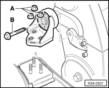
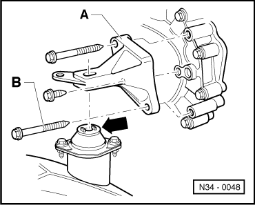
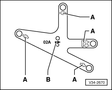
To do this remove gearbox console securing bolt -B- as follows:
|
 |
|
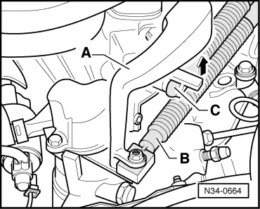
Note: Do not damage P.A.S. pipe when moving engine/gearbox assembly. |
 |
|
Note: Do not damage P.A.S pipe when lowering gearbox. |
 |
|
|
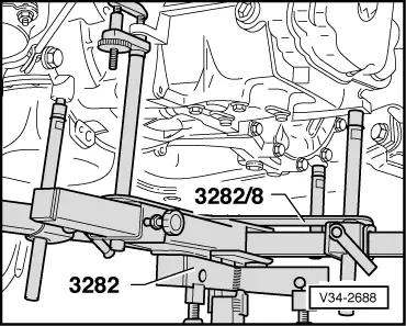
Transporting the gearbox
|
 |
|
|
Notes:
|
 |
|
The clutch plate must be able to slide lightly to and fro on the input shaft.
|
 |
|
|
|
|
Note: Do not damage P.A.S pipe.
|
|
|
Install gearbox console securing bolt -B- as follows:
|
 |
|
|
=> Repair group 27; Removing and installing starter.
|
|
|
|
|
|
|
|
|
|
|
|
|
|
|
|
|
|
|
|
|
|
|
|
|
|
|
|
 |
|
=> Repair group 21; Removing and installing parts of turbocharger
Note: Note radio coding for vehicles with coded radio.
Tightening torques |
 |
|||||||||||||||||||||||||
|
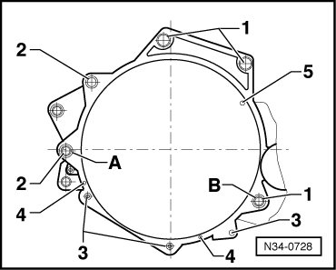
→ Gearbox to engine
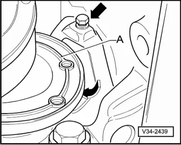
1) Also starter to gearbox 2) Only on engines with an aluminium sump, 3) Large cover plate for flywheel only on engines with heat steel sump (sump painted black) 4) Small cover plate for flywheel Items A + B - Dowel sleeves |
 |
|||||||||||||||||||
|
→ Assembly mountings
| |||||||||||||||||||
|
||||
|
→ Gearbox console to body
|
|
|||||||||||||
|
→ Engine console to body
| |||||||||||||