
Golf Mk3
 Note
Note
|

| 1 - | Gearbox housing |
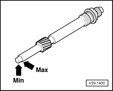
| 2 - | Speedometer drive |
| q | With marking for indicating oil level → Fig. |
| 3 - | Output shaft for drive flange |
| q | Install with thread facing drive flange |
| q | Remove before removing differential |
| q | Install only after adjusting differential |
| 4 - | O-ring |
| q | Always renew |
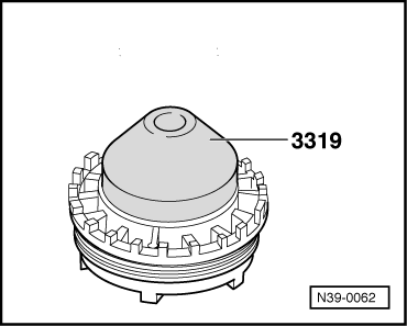
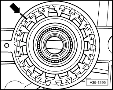
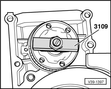
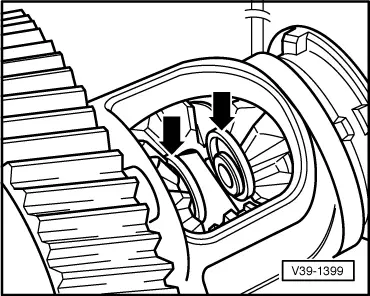
| 5 - | Adjusting ring |
| q | Removing → Fig. |
| q | If used bearings are to be refitted, mark installation position before removal and reinstall in marked position → Fig. |
| q | When installing new bearings, pay attention to adjustment instructions ⇒ Adjusting differential, → Chapter |
| 6 - | Drive flange oil seal |
| q | Before installing, pack space between sealing lips with multi-purpose grease |
| q | Can be renewed with gearbox installed → Chapter |
| q | Remove with oil seal extractor lever -VW 681- |
| q | Driving in → Fig. |
| 7 - | Tapered ring |
| q | Shoulder faces thrust washer |
| 8 - | Thrust washer |
| q | Place over compression spring |
| 9 - | Compression spring |
| 10 - | Drive flange |
| q | Insert with tapered ring, thrust washer and compression spring |
| q | Remove before removing inner retaining ring on differential bevel gear |
| q | Removing and installing → Fig. |
| 11 - | Dished washer |
| 12 - | Retaining ring |
| 13 - | Sealing cover |
| 14 - | Locking element |
| 15 - | Bolt, 12 Nm |
| 16 - | Sealing cover |
| 17 - | Retaining ring |
| 18 - | Dished washer |
| 19 - | Drive flange |
| q | Insert with tapered ring, thrust washer and compression spring |
| q | Remove before removing inner retaining ring on differential bevel gear |
| q | Removing and installing → Fig. |
| 20 - | Compression spring |
| 21 - | Thrust washer |
| q | Place over compression spring |
| 22 - | Tapered ring |
| q | Shoulder faces thrust washer |
| 23 - | Drive flange oil seal |
| q | Before installing, pack space between sealing lips with sealing grease -G 052 128- |
| q | Can be renewed with gearbox installed → Chapter |
| q | Remove with oil seal extractor lever -VW 681- |
| q | Driving in → Fig. |
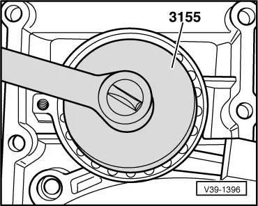
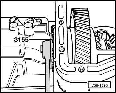
| 24 - | Bearing body, 150 Nm |
| q | When installing new bearings, pay attention to adjustment instructions ⇒ Adjusting differential, → Chapter |
| q | Remove using slotted nut wrench -3155- |
| q | Installing → Fig. |
| 25 - | O-ring |
| q | Always renew |
| 26 - | Output shaft for drive flange |
| q | Install with thread facing drive flange |
| q | Remove before removing differential |
| q | Install only after adjusting differential |
| 27 - | Differential |
| q | Dismantling and assembling → Chapter |
| q | Before removing differential, take out bearing body, adjusting ring and output shafts |
| 28 - | Bolt, 12 Nm |
| 29 - | Locking element |
| 30 - | Retaining ring |
| q | First remove drive flange before removing retaining ring |
| q | Removing and installing → Fig. |
| 31 - | Retaining ring |
| q | First remove drive flange before removing retaining ring |
| q | Removing and installing → Fig. |
| 32 - | Seal |
| q | Always renew |
| 33 - | Cover |
| q | For differential |
| 34 - | Bolt, 28 Nm |
| q | Insert with locking fluid -AMV 185 101 A1- |
Note| After adjusting tapered roller bearings, secure bearing body and adjusting ring. |
|
|
|
|
|
|
Note
|
|
|
|
|
|
|
|