
Golf Mk3
|
Dismantling and assembling engine
Adjusting valve timing
|
 |
|
|
Work sequence Engine removed Install single chain and chain tensioner with tensioning plate: |
|
|
Vehicles with manual gearbox
Vehicles with automatic gearbox
|
 |
|
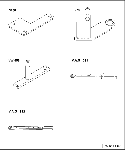
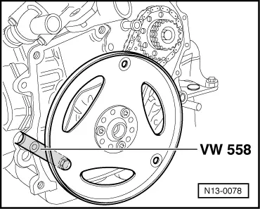
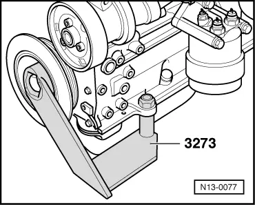
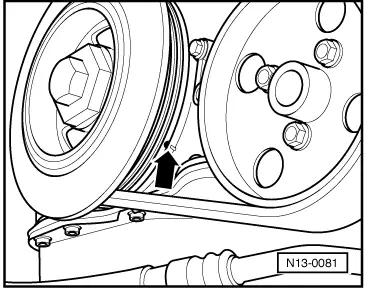
Note: On vehicles 08.95 ▸gearbox housing is installed without a cut-out forTDC mark. Therefore the vibration damper is marked with aTDC No. 1 cylinder mark. To prevent crankshaft from turning, e.g. when securing the flywheel or drive plate the counter-hold 3273 can be used. |
 |
|
|
|
|
|
Continuation for all vehicles
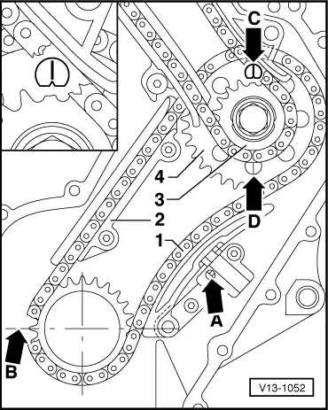
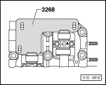
Install camshaft chain and chain tensioner with tensioning plate: |
 |
|
Note: With cylinder head removed:
Notes:
|
 |
|
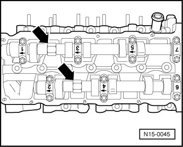
→ Note: Only counter-hold with 24 mm open jaw spanner on the camshaft -arrow-. The camshaft jig must not be fitted when tightening/loosening the sprockets.
Notes:
|
 |
|
Engine installed, cylinder head removed
|
 |
|
|
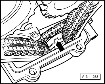
→ If the TDC No. 1 Cyl. setting is correct it is possible to see a notch on the intermediate shaft sprockets -arrow-. If the notch cannot be seen:
Note: If the crankshaft is turned with the cylinder head removed, a 2nd mechanic should guide the double chain by hand to prevent it jamming. |
|
|
Notes:
|
|
|
|
→ Note: Only counter-hold with 24 mm open jaw spanner on the camshaft -arrow-. The camshaft jig must not be fitted when tightening/loosening the sprockets.
Notes:
|