
Golf Mk3
|
Servicing power assisted steering
Dismantling and assembling power assisted steering box (ZF)
|
 |
|
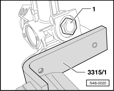
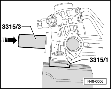
Note: Use vice clamps, check vice clamps for impurities e.g. metal filings or similar and thoroughly remove. If a spanner face is present on the rack then use an open jaw spanner to counter hold. The rack should not then be tensioned in a vice. |
 |
|
Notes:
|
 |
|
|
 |
|
|
 |
|
|
 |
|
|
 |
|
|
 |
|
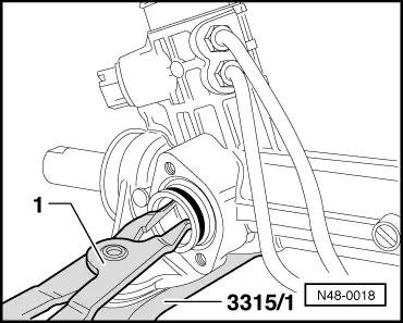
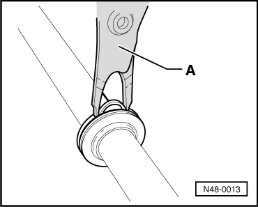
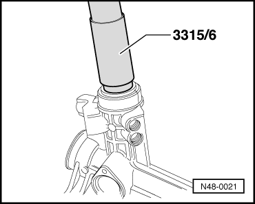
When fitting the puller -A- ensure that the claws (arrows on illustration N-48-0058 Page 48-97) locate properly under the roller bearing. The puller must not be spread too far otherwise the roller bearing seat in the housing will be damaged or the roller bearing can jam in the housing. |
 |
|
|
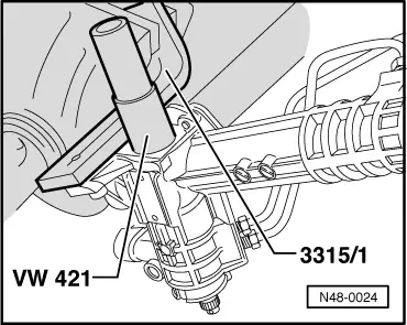
→ To ease fitting the puller it is recommended that a rubber band is placed around the claws, for ease of illustration the figure shows the housing sectionalised.
Removing valve body oil seal |
|
|
When inserting the puller -A- ensure that the claws (arrows on illustration N-48-0058 Page 48-97) locate properly under the oil seal. The puller must not be spread too far otherwise the oil seal seat in the housing will be damaged or the oil seal can jam in the housing. |
 |
|
|
→ To ease fitting the puller it is recommended that a rubber band is placed around the claws, for ease of illustration the figure shows the housing sectionalised.
Removing inner seal for rack. |
 |
|
|
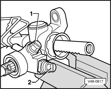
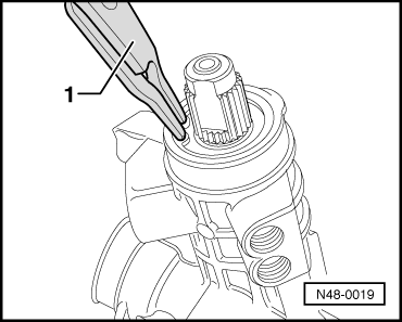
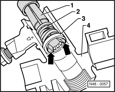
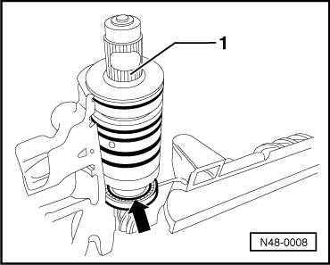
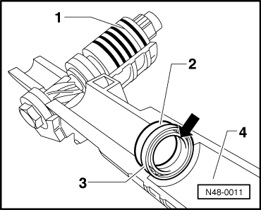
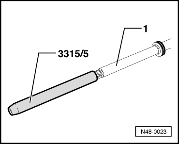
Install seal for valve body → The sealing lip (arrow) faces upwards to valve body splines -1-. For ease of illustration figure shows the housing sectionalised with valve body installed. The valve body for ease of illustration is lifted slightly. |
 |
|
 |
|
 |
|
|
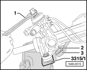
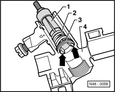
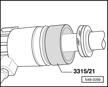
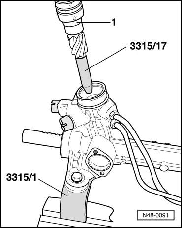
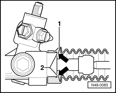
Installing rack inner oil seal → The seal -3- lip (arrow) points to cylinder -4-
For ease of illustration the housing is shown sectionalised. |
 |
|
|
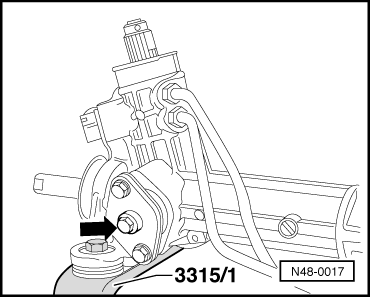
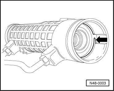
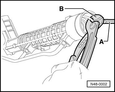
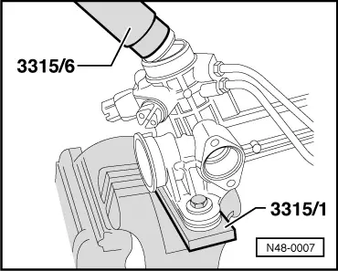
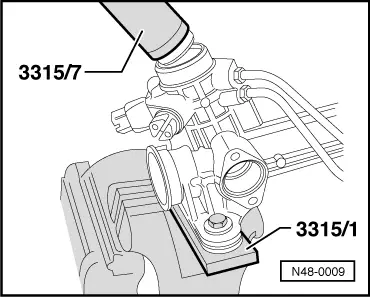
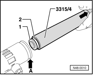
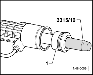
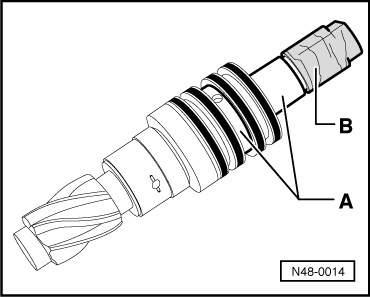
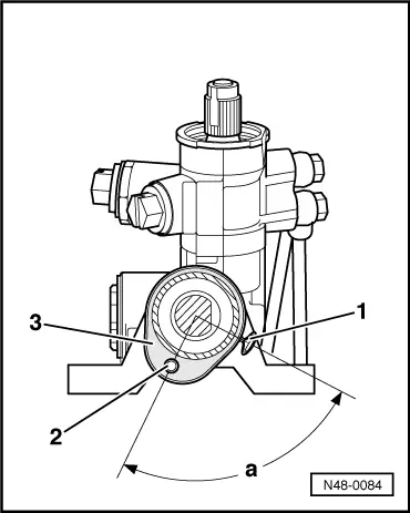
When the groove (arrow) on the tool aligns with the housing edge (arrow A) then the seal is seated correctly. |
 |
|
|
When the seal is replaced it must be replaced with a new seal of the same colour! Is already fitted to new racks which are supplied as replacement part
Observe allocation of O-ring to seal! Is already fitted to new racks which are supplied as replacement part
|
 |
|
Fitting the rack
|
 |
|
No grease must be allowed to get into the oil circuit!
|
 |
|
When sliding in ensure that the seal is pressed into the groove in the piston without jamming.
|
 |
|
|
 |
|
|
Ball bearing must not be canted when driving in |
 |
|
Ensure that the seal in the housing is not damaged by the pinion teeth! |
 |
|
|
 |
|
|
 |
|
Install track rods |
|
|
Note: Use vice clamps, check vice clamps for impurities e.g. metal filings or similar and thoroughly remove. Installing bellows
Note: |
 |
|
|
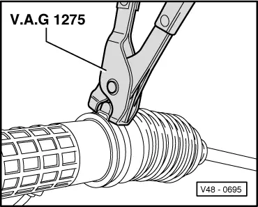
Ensure that the bellows and the pressure balancing pipe are correctly installed,, => Bellows installation position. → Bellows installation position
When installing the bellows ensure that the lip (arrow) lies against the housing. |
 |
|
|
→ Clamp installation position
|
 |
|
Only use original hose clamps |