
Golf Mk3
|
 Note
Note| t | Renew self-locking nuts and bolts. |
| t | Welding and straightening work on steering components is not permitted. |
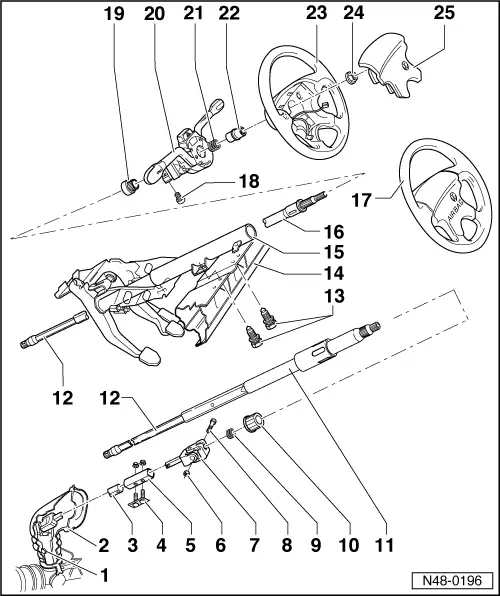
| 1 - | Hexagon bolt, 30 Nm |
| 2 - | Protective sleeve |
| 3 - | Lower universal joint |
| q | Modified toothing as of chassis No. 1HN 002 450 → Chapter. |
| 4 - | Connecting piece |
| 5 - | Connecting sleeve |
| 6 - | Hexagon nut, 30 Nm |
| 7 - | Upper universal joint |
| 8 - | Hexagon bolt |
| 9 - | Spring |
| 10 - | Lower steering column bearing |
| q | Pull in with multi-purpose tool -VW 771- and large washer. |
| q | Drive out downwards with a tube. |
| 11 - | Steering column |
| q | With torque overload clutch, cannot be dismantled. |
| q | Standard for convertible as of model year 97. |
| If a moment of over 100 Nm is exerted on steering wheel then the steering column will also turn without damaging the locking pin. |
| The straight-ahead position is not changed as a result. |
| Can be retrofitted in all models. |
| The relevant column tube and steering column switch must also be used on retrofitting. |
| 12 - | Steering column lower section |
| q | Remove by pulling upwards out of column tube. |
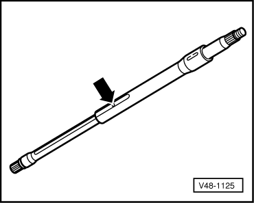
| q | Check length → Fig.. |
| q | Supplied complete as spare part with upper section. |
| 13 - | Shear-head bolt |
| q | Tighten until head shears off. |
| q | Drill out to remove. |
| 14 - | Assembly carrier |
| 15 - | Column tube |
| Lower bracket must lie fully on pedal cluster bearing. |
| For steering column with torque overload clutch, longer cut-out on bottom of tube. |
| 16 - | Steering column upper section |
| q | Remove by pulling upwards out of column tube. |
| q | Supplied complete as spare part with lower section. |
| 17 - | Steering wheel for airbag |
| q | Removing and installing → Chapter. |
| 18 - | Shear-head bolt |
| q | Checking distance between steering wheel and steering lock housing trim before tightening → Fig.. |
| q | Drill out to remove. |
| 19 - | Support ring |
| 20 - | Steering column switch |
| q | Repairing → Electrical system; Rep. Gr.96. |
| q | Adjusting steering wheel/steering lock housing distance → Fig.. |
| Different version for steering column with torque overload clutch → Electronic parts catalogue “ETKA”. |
| 21 - | Spring |
| 22 - | Splined adapter sleeve |
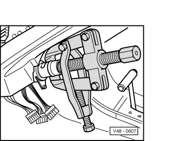
| q | Pulling off → Fig. |
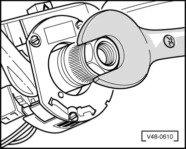
| q | Installing → Fig.. |
| 23 - | Steering wheel |
| q | Install in central position. |
| 24 - | Hexagon nut, 50 Nm |
| 25 - | Cover cap |
|
|
|
|
|

|