
Golf Mk4
|
Dismantling and assembling selector forks
Dismantling and assembling selector forks
|
 |
|
|
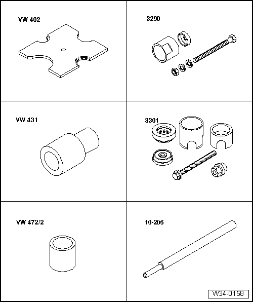
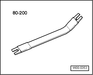
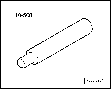
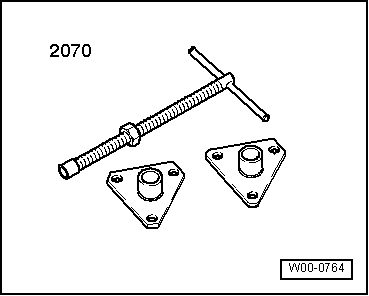
Special tools, workshop equipment, testers, measuring instruments and auxiliary items required
|
 |
|
Special tools, workshop equipment, testers, measuring instruments and auxiliary items required |
 |
|
|
 |
|
|
Note:
|
|
|
|
|
|
 |
|
|
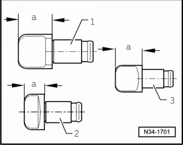
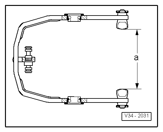
→ Fig.1 Identifying selector segments Dimension -a- 1 - 1st and 2nd gear selector segments = 12.1 mm 1st and 2nd gear selector segments in combination with modified synchronisation (=> page 35-52 ) = 11.4 mm Shorter selector segments can also be installed in older generation gearboxes. 2 - 3rd and 4th gear selector segments = 7.7 mm 3 - 5th gear selector segments = 12.1 mm |
 |
|
|
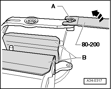
→ Fig.2 Removing lock washer
|
 |
|
|
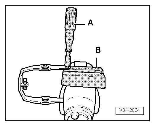
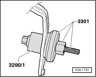
→ Fig.4 Removing angular contact ball bearing Note: When removing and installing the inner races, do not bend selector forks. |
 |
|
|
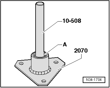
→ Fig.5 Pressing angular contact ball bearing inner race -A- into outer race The inner race must engage with outer race. |
 |
|
|
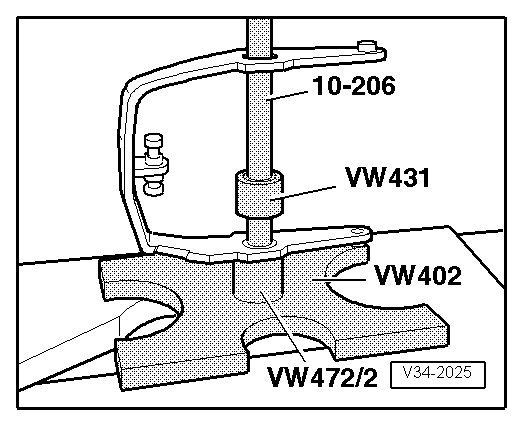
→ Fig.6 Pulling angular contact ball bearing into selector fork onto limit stop The press piece recess 3290/1 faces towards ball bearing. |
 |
|||||||||
|
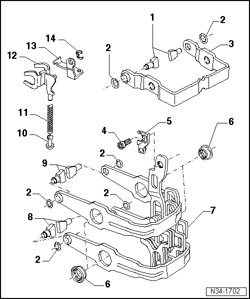
→ Fig.7 Selector fork with selector segments installed
Selector segment assignment => Fig.1 . |