volkswagen Workshop Repair Guides

Volkswagen Workshop Service and Repair Manuals

Dismantling and assembling procedure for gearboxes from gearbox date 19 05 3 > < Removing
Installing
Installing
   
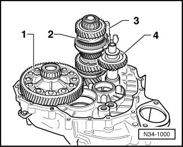
–  Insert differential -1-.
–  Install output shaft for 5th, 6th and reverse gears -2- together with reverse gear selector fork, selector rod for 5th and 6th gears -3- and reverse shaft -4-.
  N34-1000
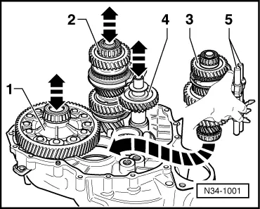
–  Take output shaft for 1st through 4th gears -3- with selector rods -5- in the right hand as shown in figure.
–  With the left hand, lift differential slightly.
–  At the same time, a 2nd mechanic must slightly lift output shaft for 5th, 6th and reverse gears -2- together with reverse gear shaft -4-.
–  Now insert output shaft for 1st through 4th gears in direction of arrow.
The teeth of the output shafts must mesh with the final drive input gear of differential.
–  Now, together with a second mechanic, place shafts in their bearing seats.
  N34-1001
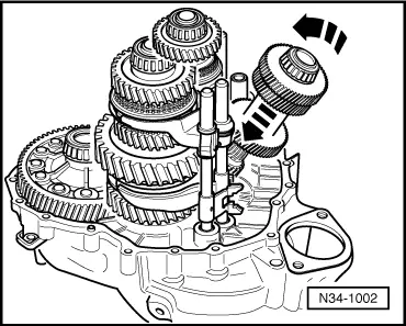
–  Set input shaft in clutch housing and swing in -arrow-.
  N34-1002
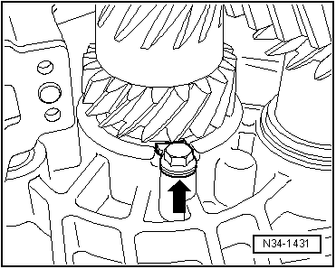
From gearbox date 06 04 0
–  Insert locking plate -arrow- in recess of tapered roller bearing outer race for input shaft.
–  Tighten new bolt to specified torque → Item.
Continued for all gearboxes
–  Fit gearbox housing.
  N34-1431
Install selector shaft as follows:
–  Move selector rods to neutral.
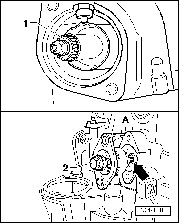
–  Insert selector shaft -1-.
–  Position selector shaft so that shift fingers are inserted in selector rods → Fig..
–  When doing this, align lower selector shaft bearing -arrow- through drilling for cover plate.
–  Bolt cover plate -A- to lower selector shaft bearing -1- with bolt -2- M8 x 60 mm.
  N34-1003
–  Hand tighten cover plate -A- by alternately tightening (1/2 turn) bolts -arrows-.
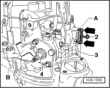
–  Remove bolt -2- and hand-tighten original bolt in its place.
–  Install selector mechanism cover -B- and tighten hexagon bolts -4- to specified torque.
–  Now tighten hexagon bolts for cover plate.
–  Insert securing bolt -3- for selector shaft guide with locking fluid -D 000 600 A2-.
–  Install reversing light switch.
–  Install left flange shaft together with spring, thrust washer and tapered ring.
–  Install speedometer sender.
  N34-1004
–  Drive in input shaft oil seal.
–  Fit slave cylinder with release bearing.
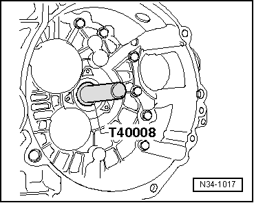
Install bevel box as follows:
  N34-1017
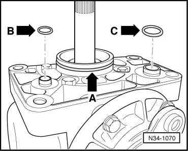
–  Always renew O-ring for sealing bevel box and gearbox -arrow A- and O-rings for sealing sleeves for oil supply system -arrow B- and -arrow C-, lightly coating with oil.
–  Grease splines of differential with grease for clutch plate splines -G 000 100-.
–  Push bevel box completely onto gearbox, ensuring that splines of bevel box input shaft are guided centrally onto differential connecting piece.
–  Align splines of right flange shaft and differential bevel gear, turning flange shaft if necessary.
–  If splines are correctly positioned and shafts are centred, then bevel box will slide to stop against gearbox.
–  Do not use securing bolts to pull bevel box onto gearbox, or bevel box will cant and bolt holes can break off.
  N34-1070
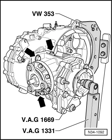
–  Install four bevel box/gearbox connecting bolts (only three shown in figure) -arrows-.
–  Tighten right flange shaft countersunk bolt with socket -V.A.G 1669- or commercially available 6 mm socket insert and hold against turning with drift.
  N34-1092

Dismantling and assembling procedure for gearboxes from gearbox date 19 05 3 > < Removing