
Golf Mk4
|

| Special tools and workshop equipment required |
| t | Support plate -VW 309- |
| t | Support clamp -VW 313- |
| t | Gearbox support -VW 353- |
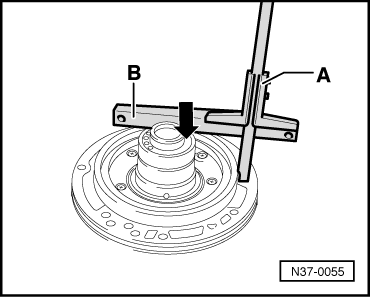
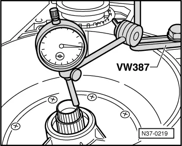
| t | Universal dial gauge bracket -VW 387- |
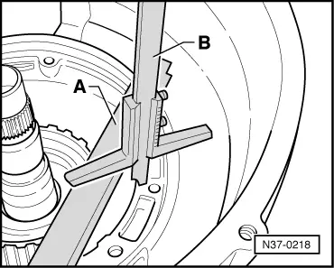
| t | Depth gauge |
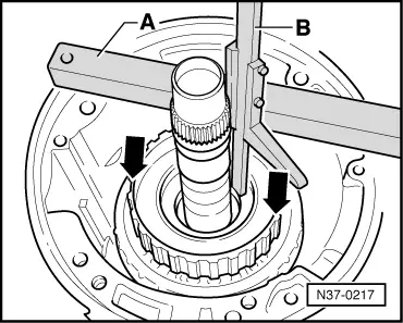
| t | Straightedge |
| t | Dial gauge |
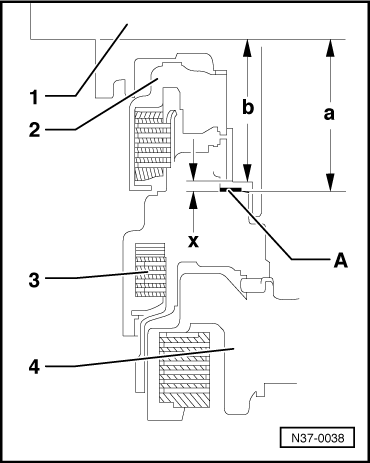
| – | To adjust clutch play, install components without shim → Item ⇒ Assembling planetary gearbox → Chapter. |

| 1 - | Gearbox housing |
| q | → Planetary gearbox installed up to small input shaft ⇒ Assembling planetary gearbox → Chapter. |
| 2 - | Needle thrust bearing with washer |
| q | Needle thrust bearing faces small input shaft |
| q | Washer faces towards -K3-. |
| 3 - | 1st to 3rd gear clutch -K1- and 3rd and 4th gear clutch -K3- with turbine shaft |
| q | In some gearboxes, → clutches -K1- and -K3- may be pressed together as shown here. |
| q | There are two different types of turbine shaft, depending on the torque converter installed → Chapter. |
| 4 - | Shims |
| q | Do not install when adjusting clutch play |
| q | Up to 3 shims can be installed |
| q | Shims are colour-coded according to thickness |
| 5 - | Reverse gear clutch -K2- |
| q | Does not need to be installed for determining the shim(s) |
| q | Install for check measurement. |
|
|
|
|
|
|
|
| Measured value 1 | = | 88.5 mm |
| - Measured value 2 | = | -34.3 mm |
| Calculated value a | = | 54.2 mm |
|
|
|
| Measured value | = | 70.5 mm |
| - Straightedge | = | -19.5 mm |
| Calculated value b | = | 51.0 mm |
|
| Gap-x- (mm) | Thickness of required shims (mm) | Colour of required shims |
| … 2.54 2.55 … 3.09 3.10 … 3.49 | 1.4 1 + 1 1.2 + 1.2 | White Blue + blue Green + green |
| 3.50 … 3.89 3.90 … 4.29 4.30 … 4.69 | 1.4 + 1.4 1.6 + 1.6 1.8 + 1.8 | White + white Black + black Grey + grey |
| 4.70 … 5.04 5.05 … 5.25 | 1.2 + 1.2 + 1.6 1.2 + 1.2 + 1.8 | Green + green + black Green + green + grey |
|
| Blue | = | 1.0 mm |
| Green | = | 1.2 mm |
| White | = | 1.4 mm |
| Black | = | 1.6 mm |
| Grey | = | 1.8 mm |
|
|
|