volkswagen Workshop Repair Guides

Volkswagen Workshop Service and Repair Manuals

Motronic injection and ignition system (2.0 ltr. engine) > < Checking knock sensors
Motronic injection and ignition system (5-cyl. engine)
Servicing ignition system
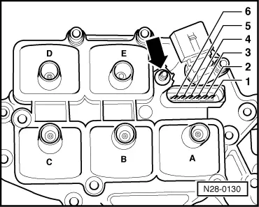
Checking ignition coils with output stage
 
W00-0431

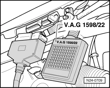
Perform check only when performance is poor or engine is shaking because its misfiring.

Special tools, testers, measuring instruments and auxiliary items required

  • ◆ → Hand multimeter V.A.G 1526 or multimeter V.A.G 1715
 
W00-0514
  • ◆ → V.A.G 1598/22 test box
  • ◆ Diode test lamp V.A.G 1527
  • ◆ Adapter set V.A.G 1594
  • ◆ Current flow diagram

Check conditions

 
N24-0588
  • ● → Fuse 32 must be OK.
  • ● All spark plugs and ignition wiring must be OK.
  • ● The battery voltage must be at least 11.5 V.
  • ● Engine speed sender must be OK, checking Page 24-57 .
  • ● Hall sender OK, checking
 
N28-0127

Test sequence

  • ‒ Switch off ignition.
  • ‒ → Pull black 6 pin connector off ignition coils -arrow-.

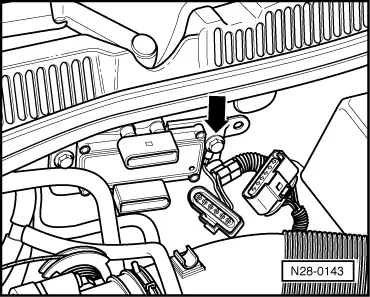
Checking voltage supply

 
N28-0130
  • ‒ → Measure supply voltage between supply voltage connection (arrow) and engine earth with multimeter and auxiliary cable from V.A.G 1594.
  • ‒ Switch on ignition.
         Specification: min. 11.5 V
  • ‒ Switch off ignition.

If no voltage was present:

  • ‒ Check wiring to fuse 29 using current flow diagram.

If the voltage was at least 11.5 V:

Checking primary resistance

 
N28-0130
  • ● Ignition switched off
  • ‒ → Measure primary resistance between connection (arrow) and connector contact 2 using multimeter and auxiliary cable from V.A.G 1594.
         Specification: Max. 100 ω
  • ‒ Repeat test at connector contacts 3...6.

If the specifications are not obtained:

  • ‒ Replace ignition coils.

If the specifications are obtained:

 
N28-0143

Checking activation

  • ● Ignition switched off
  • ‒ → Pull the black and brown 6 pin connectors off the output stage N122.
 
N28-0128
  • ‒ → Check wiring 1...6 between ignition coils 6 pin connector and black 6 pin connector on output stage (N122) for open circuit using current flow diagram.
         Wire resistance: Max. 1.5 ω

If no wiring fault is detected:

  • ‒ Additionally check wires for short to one another.
         Specification: ∞ω
 
N28-0143
  • ‒ → Check that the earth connection is properly secured on the heat sink for the output stage (arrow).
  • ‒ Measure the voltage supply at the brown 6 pin connector for the output stage:
  • ‒ Connect diode test lamp V.A.G1527 with auxiliary cables from V.A.G 1594 to contact 1 of brown 6 pin connector and vehicle earth:
  • ‒ Switch on ignition.

The LED must light up.

  • ‒ Switch off ignition.

If the LED does not light up:

  • ‒ Check wiring from connector contact 1 of brown 6 pin connector to fuse 29 using current flow diagram.

If not open circuit can be found:

  • ‒ Connect diode test lamp V.A.G1527 to brown 6 pin connector contact 2 and the vehicle battery positive terminal:
  • ‒ Switch on ignition.

The LED must light up.

  • ‒ Switch off ignition.
  • ‒ Repeat test on connector contacts 3...6.
 
N24-0709

If the activation of the output stage is fault-free:

  • ‒ Switch off ignition.
  • ‒ Replace output stage (N122).

If the activation of the output stage is interrupted at one or more connector contacts:

  • ‒ → Connect test box V.A.G 1598/22 to control unit wiring harness.
 
N28-0143
  • ‒ → Check wiring between brown 6 pin connector and test box for open circuits.
         Contact 1+socket 1
         Contact 2+socket 71
         Contact 3+socket 57
         Contact 4+socket 77
         Contact 5+socket 70
         Contact 6+socket 78
         Wire resistance: Max. 1.5 ω

If no wiring fault is detected:

  • ‒ Reconnect the detached connectors.
  • ‒ Replace engine control unit
    .

Motronic injection and ignition system (2.0 ltr. engine) > < Checking knock sensors