volkswagen Workshop Repair Guides

Volkswagen Workshop Service and Repair Manuals

Checking fuel pressure regulator and holding pressure > < Removing and installing injectors
Motronic injection and ignition system (5-cyl. engine)
Checking components
Checking injectors
 
W24-0007

Special tools, workshop equipment, test and measuring appliances and aux. items required

  • ◆ 3277 A Fitting tool
  • ◆ 3411 Guide rods
  • ◆ V.A.G 1348/3 Remote control
  • ◆ V.A.G 1348/3-2 Adapter
  • ◆ V.A.G 1602 Calibration tester
  • ◆ V.A.G 1526 Hand multimeter
  • ◆ V.A.G 1551 Fault reader
  • ◆ V.A.G 1594 Adapter set
  • ◆ V.A.G 1598/22 Test box
  • ◆ Current flow diagram

This check should only be carried out when a fault in the fault number range "01249 ... 01253" is present, or a fault is detected during the final control diagnosis.

 
N24-0588

Check conditions

  • ● Engine speed sender OK.
  • ● Fuel pump relay OK
  • ● → Fuses 28 and 32 must be OK.

Test sequence

  • ‒ Check activation of injector via final control diagnosis first .

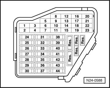
If one or more injectors do not click:

Checking voltage supply

Note:

The positive supply for the injectors is a direct feed from the fuel pump relay (J17) via fuse 32 to the injectors.

  • ‒ Switch off ignition.
  • ‒ Pull the fuel pump relay (J17) out of its relay location.

=> Current flow diagrams, Electrical fault finding and Fitting locations binder

  • ‒ Connect the remote control V.A.G 1348/3 with adapter cable V.A.G 1348/3-2 to the battery (+) and chamber 23 of relay location.
  • ‒ Operate the remote control and check the voltage supply between fuse 32 and vehicle earth.
         Specification: 10...15 V
 
N24-0709

If no voltage was present:

  • ‒ Check the wiring from fuse 32 to relay plate using current flow diagram:

=> Current flow diagrams, Electrical fault finding and Fitting locations binder

  • ‒ → Connect test box V.A.G 1598/22 to control unit wiring harness.
  • ‒ Connect the multimeter using adapter cables from V.A.G 1594 between the test box sockets 2 and 73 to check injector No. 1 Cyl.
  • ‒ Operate the remote control and check the voltage at the injector.
         Specification: 9...12 V
  • ‒ Repeat the check for injectors Cyls. No. 2...5
         Contacts 2+80 for No. 2 Cyl. injector
         Contacts 2+58 for No. 3 Cyl. injector
         Contacts 2+65 for No. 4 Cyl. injector
         Contacts 2+72 for No. 5 Cyl. injector

If the specifications are not obtained:

Checking activation

  • ‒ Remove the intake manifold upper part to gain access to the connectors for the injectors. To do this:
  • ◆ Remove spark plug connectors with 3277A.
  • ◆ Remove the engine covers.
  • ◆ Bring the lock carrier into the service position,

=> General body repairs; Repair group 50; Body front; lock carrier service position

  • ◆ Remove the intake hose between throttle valve control part and air mass meter.
  • ◆ Pull the connector off the throttle valve control part and detach the earth wire to cylinder head.
  • ◆ Disconnect the throttle valve control part from the coolant circuit, disconnect the accelerator cable and pull off the connector for the intake manifold temperature sender.
  • ◆ Pull off the vacuum connection on intake manifold upper part and the vacuum hose on the intake manifold change-over actuating element.
  • ◆ Remove the intake manifold supports on right and left, and then remove the intake manifold upper part from the intake manifold manifold lower part.
  • ‒ Take off intake manifold upper part and place it on a suitable surface so that the vacuum actuating element is not damaged.

Note:

Seal the intake channels in the intake manifold lower part and/or in cylinder head with clean cloths.

  • ‒ Pull the connectors off the injectors.
 
N24-0588
  • ‒ Check the wiring between the test box and connector contact for open circuit.
         Injector 1: Contact 2+socket 73
         Injector 2: Contact 2+socket 80
         Injector 3: Contact 2+socket 58
         Injector 4: Contact 2+socket 65
         Injector 5: Contact 2+socket 72
         Wire resistance: Max. 1.5 ω
  • ‒ → Pull fuse 32 out of its fitting location and check the wire resistance tween contact 32a and connector contact 1 on No. 1 Cyl. injector connector
         Wire resistance: Max. 1.5 ω
  • ‒ Repeat the test on the other four injectors.
 
N24-0231

If the specifications are not obtained:

  • ‒ → Check the wiring from contact 2 to control unit and contact 1 to fuel pump relay using current flow diagram:

=> Current flow diagrams, Electrical fault finding and Fitting locations binder

 
N24-0228

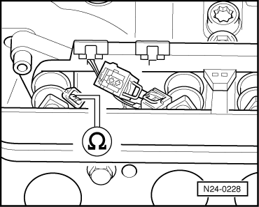
Checking resistance of injectors

  • ‒ → Check resistance of injectors between contacts.
         Specification: 15.0...21.5 ω

When the engine is warm the resistance will be approx. 4...6 ωhigher.

If the specification is not attained:

  • ‒ Renew defective injector

Note:

Always renew seals.

 
W24-0004

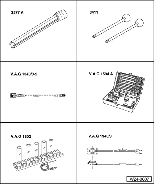
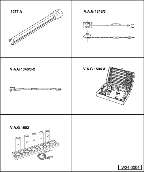
Check injectors for leaks and quantity injected

Special tools, workshop equipment, test and measuring appliances and aux. items required

  • ◆ 3277 A Fitting tool
  • ◆ V.A.G 1348/3 Remote control
  • ◆ V.A.G 1348/3-2 Adapter
  • ◆ V.A.G 1594 Adapter set
  • ◆ V.A.G 1602 Calibration tester

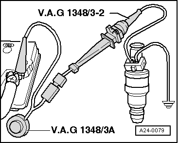
Checking for leaks

Test sequence

  • ‒ To remove the injectors the upper part of the intake manifold must be removed. To do this:
  • ◆ Remove spark plug connectors with 3277A.
  • ◆ Remove the engine covers.
  • ◆ Bring the lock carrier into the service position,

=> General body repairs; Repair group 50; Body front; lock carrier service position

  • ◆ Remove the intake hose between throttle valve control part and air mass meter.
  • ◆ Pull the connector off the throttle valve control part and detach the earth wire to cylinder head.
  • ◆ Disconnect the throttle valve control part from the coolant circuit, disconnect the accelerator cable and pull off the connector for the intake manifold temperature sender.
  • ◆ Pull off the vacuum connection on intake manifold upper part and the vacuum hose on the intake manifold change-over actuating element.
  • ◆ Remove the intake manifold supports on right and left, and then remove the intake manifold upper part from the intake manifold manifold lower part.
  • ‒ Take off intake manifold upper part and place it on a suitable surface so that the vacuum actuating element is not damaged.

Note:

Seal the intake channels in the intake manifold lower part and/or in cylinder head with clean cloths.

  • ‒ Remove fuel rail complete with injectors => Page 24-17 .
  • ‒ Place fuel rail down so that valve openings do not contact other components.
  • ‒ Connect the fault reader V.A.G 1551 (V.A.G 1552) and with ignition switched on select engine electronics control unit with the "Address word" 01.
    (Connecting fault reader and selecting engine electronics control unit => Page 01-4 .)
  • ‒ Initiate the final control diagnosis up to activating No. 1 cylinder injector .

The fuel pump must audibly build up fuel pressure.

Note:

Initiating the final control diagnosis enables the fuel pump to run when the engine is stationary. The idling switch must remain closed otherwise the selected injector sprays 5 times.

A maximum of 1 to 2 drops may leak per minute when fuel pump is running (visual check).

If the fuel loss is greater:

  • ‒ Terminate final control diagnosis.
  • ‒ Switch off ignition.
 
A24-0079
  • ‒ Replace defective injector , item 8 .

Checking quantity injected

  • ‒ Insert each injector in a measuring glass from injected quantity test unit V.A.G 1602.
  • ‒ → Place a contact of the injector to be tested to engine earth using an auxiliary cable from V.A.G 1594.
  • ‒ Connect second injector contact to remote control V.A.G 1348/3A with adapter cable V.A.G 1348/3-2.
  • ‒ Connect crocodile clip to battery (+).
  • ‒ Initiate final control diagnosis and activate No. 1 cylinder injector (N30) => Page 01-86 ; the fuel pump must run.
  • ‒ Operate remote control V.A.G 1348/3A for 30 seconds.
  • ‒ Repeat the test on the other four injectors.
  • ‒ After the injectors have been activated, place the five measuring classes in V.A.G 1602 onto a flat level surface and compare the quantities injected.
         Specification: 90...125 ml for each injector

If the measured values of one or more injectors lie above or below the prescribed specifications:

  • ‒ Replace the defective injector , item 8 .
  • ‒ Repeat check on injectors.

Installing the injectors is performed logically in reverse order. But note the following:

  • ◆ Renew O-rings on all injectors and moisten lightly with engine oil.
  • ◆ Insert injectors vertically and correctly positioned into fuel rail and secure with retaining clips.
  • ◆ Press fuel rail with injectors securely attached evenly into intake manifold lower part.

Checking fuel pressure regulator and holding pressure > < Removing and installing injectors