volkswagen Workshop Repair Guides

Volkswagen Workshop Service and Repair Manuals

Checking throttle valve control part > < Checking Lambda probe heating
Simos injection and ignition system
Checking components
Checking air mass meter

Special tools, workshop equipment, testers, measuring instruments and auxiliary items required

  • ◆ Fault reader V.A.G 1551 or vehicle system tester V.A.G 1552 with cable V.A.G 1551/3
  • ◆ Test box V.A.G 1598/22
  • ◆ Hand multimeter V.A.G 1526 or multimeter V.A.G 1715
  • ◆ Adapter set V.A.G 1594
  • ◆ Current flow diagram

Test conditions

 
N24-0588
  • ● → Fuse 43 must be OK.
  • ● Coolant temperature at least 80 °C
  • ● All electrical consumers, e.g. lights and rear window heating must be switched off
  • ● If the vehicle is equipped with an air conditioner, this must be switched off.
  • ● On vehicles with automatic gearbox selector lever in "P" or "N" position

Test sequence

  • ‒ Connect fault reader V.A.G 1551 (V.A.G 1552). Start engine and select "Address word" 01 of engine control unit. When doing this the engine must be running at idling speed.
    (Connecting fault reader and selecting engine control unit .)
 
→ Indicated on display:
Rapid data transfer     HELP
Select function XX
  • ‒ Press keys 0 and 8 for the function "Read measured value block" and confirm entry with Q key.
 
→ Indicated on display:
Read measured value block     HELP
Input display group number XXX
  • ‒ Press keys 0, 0 and 1 for "Display group number 1" and confirm entry with Q key.
 
→ Indicated on display:
(1...4 = Display zones)
Read measured value block     1     ⇒
     1     2     3     4
  • ‒ Check whether the coolant temperature is above 80 °C in display zone 2.
  • ‒ Change to display group 2 as follows:
         V.A.G 1551: Press key 3
         V.A.G 1552: Press key ↑
 
→ Indicated on display:
(1...4 = Display zones)
Read measured value block 2     ⇒
     1     2     3     4

Display zone 2 shows the intake air mass (milligrams per stroke).

Specification: 76...164 mg/H

  • ‒ Press the ⇒key.
  • ‒ Press keys 0 and 6 for the "End output" function and confirm input with the Q key.
  • ‒ Switch off ignition.

If the specifications are not attained or there is a fault in fault memory relating to the air mass meter:

 
N24-0701
  • ‒ → Pull 4 pin connector -1- off air mass meter -2-.
  • ‒ Connect multimeter to measure voltage on connector contacts 3 and engine earth.
  • ‒ Start engine and run at idling speed.
  •      Specification: 11...15 V
  • ‒ Switch off ignition.
  • ‒ If the voltage supply is OK, test the signal wire and earth wire => Page 24-33 .

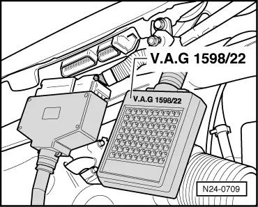
If no voltage is present:

  • ‒ Check wiring from contact 3 to fuel pump relay (J17) according to current flow diagram.

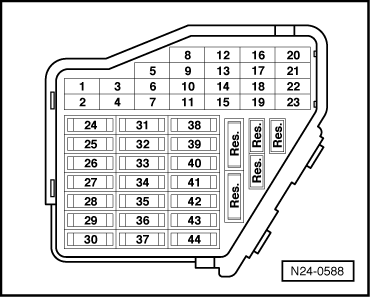
=> Current flow diagrams, Electrical fault finding and Fitting locations binder

 
N24-0709

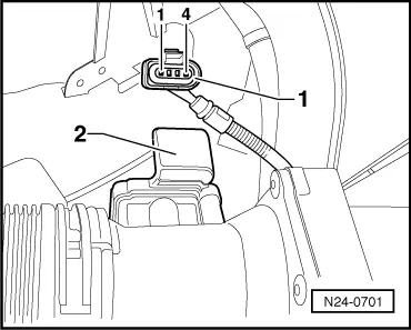
Testing signal wiring for air mass meter

  • ‒ → Connect test box V.A.G 1598/22 to control unit wiring harness.
 
N24-0701
  • ‒ → Check wiring between test box and 4 pin connector for open circuit using current flow diagram.
         Contact 1+socket 13
         Contact 2+socket 12
         Wire resistance: Max. 1.5 ω
  • ‒ Additionally check wires all for short to one another.
         Specification: ∞ω

If no wiring fault is detected:

  • ‒ Renew air mass meter (G70) with intake air temperature sender (G42) , item 2 .

Checking throttle valve control part > < Checking Lambda probe heating