volkswagen Workshop Repair Guides

Volkswagen Workshop Service and Repair Manuals

Checking coolant temperature sender > < Checking air mass meter
Simos injection and ignition system
Checking components
Checking throttle valve control part

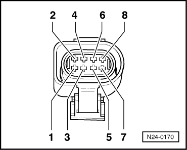
Components of the throttle valve control part (J338):
Throttle valve positioner (V60), throttle valve positioner potentiometer (G88), throttle valve potentiometer (G69) and idling switch (F60)

Note:

If the throttle valve control part is replaced, the following must be carried out:

  • ◆ Match engine control unit to the throttle valve control part
  • ◆ On vehicles with automatic gearbox: Match the gearbox control unit

=> 4-Speed automatic gearbox 01M self-diagnosis; Repair group 01; performing self-diagnosis; initiating basic setting

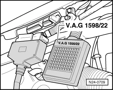
Contact pin assignment of throttle valve control part differs on vehicles with or without a cruise control system (CCS).

Identification: Steering column switch with controls for CCS.

Special tools, workshop equipment, testers, measuring instruments and auxiliary items required

  • ◆ Fault reader V.A.G 1551 or vehicle system tester V.A.G 1552 with cable V.A.G 1551/3
  • ◆ Test box V.A.G 1598/22
  • ◆ Hand multimeter V.A.G 1526 or multimeter V.A.G 1715
  • ◆ Adapter set V.A.G 1594
  • ◆ Current flow diagram

Check conditions

  • ● Earth connection between throttle valve control part and cylinder head OK.
    => Page 24-17 , item 9
  • ● Throttle valve not damaged or dirty.

Checking idling switch

  • ‒ Connect the fault reader V.A.G 1551 (V.A.G 1552). Then switch ignition on and select engine control unit with the "Address word" 01.
    (Connecting fault reader and selecting engine control unit => Page 01-4 .)
 
→ Indicated on display:
Rapid data transfer     HELP
Select function XX
  • ‒ Press keys 0 and 8 for the function "Read measured value block" and confirm entry with Q key.
 
→ Indicated on display:
Read measured value block     HELP
Input display group number XXX
  • ‒ Press keys 0, 9 and 8 for "Display Group 98" and confirm entry by pressing Q.
 
→ Indicated on display:
(1...4 = Display zones)
Read measured value block 98     ⇒
     1     2     3     4
  • ‒ Check idling switch at idling stop in display zone 3.
  • 1st position from right must display 0
         Display: 00000000
  • ‒ Slowly open throttle valve.
  • 1st position from right must display 1
         Display: 00000001

If the specifications are not obtained:

Display

Cause

Continuation of check

Always 1

Open circuit or short to positive

=> Page 24-37

Always 0

Short to earth

=> Page 24-38

Continuation of check when display is always at 1

 
N24-0170
  • ‒ → Pull 8 pin connector off throttle valve control part.
  • ‒ Bridge the following connector contacts:
         Vehicles with CCS1): Contacts 2 + 6
         Vehicles without CCS1): Contacts 3 + 7
    using auxiliary cables from V.A.G 1594 and observe display.

     1)     CCS = Cruise control system

Display 0:

  • ‒ Press the ⇒key.
  • ‒ Press keys 0 and 6 for the "End data transfer" function and confirm input with the Q key.
  • ‒ Switch off ignition.
  • ‒ Replace throttle valve control part
    , item 2 .

Display 1:

  • ‒ Press the ⇒key.
  • ‒ Press keys 0 and 6 for the "End data transfer" function and confirm input with the Q key.
  • ‒ Switch off ignition.
  • ‒ Check voltage supply of throttle valve control part and wiring to control unit => Page 24-46 .

If the voltage supply and wiring is OK:

  • ‒ Renew engine control unit => Page 24-104 .

Continuation of check when display constantly shows 0

 
N24-0170
  • ‒ → Pull 8 pin connector off throttle valve control part.

Display 1:

  • ‒ Press the ⇒key.
  • ‒ Press keys 0 and 6 for the "End data transfer" function and confirm input with the Q key.
  • ‒ Switch off ignition.
  • ‒ Replace throttle valve control part
    , item 2 .

Display 0:

  • ‒ Press the ⇒key.
  • ‒ Press keys 0 and 6 for the "End data transfer" function and confirm input with the Q key.
  • ‒ Switch off ignition.
  • ‒ Check voltage supply of throttle valve control part and wiring to control unit => Page 24-46 .

If the voltage supply and wiring is OK:

  • ‒ Renew engine control unit => Page 24-104 .

Checking operating condition

  • ‒ Connect fault reader V.A.G 1551 (V.A.G 1552). Start engine and select "Address word" 01 of engine control unit. When doing this the engine must be running at idling speed.
    (Connecting fault reader and selecting engine control unit => Page 01-4 .)
 
→ Indicated on display:
Rapid data transfer     HELP
Select function XX
  • ‒ Press keys 0 and 8 for the function "Read measured value block" and confirm entry with Q key.
 
→ Indicated on display:
Read measured value block     HELP
Input display group number XXX
  • ‒ Press keys 0, 9 and 8 for "Display Group 98" and confirm entry by pressing Q.
 
→ Indicated on display:
(1...4 = Display zones)
Read measured value block 98     ⇒
     1     2     3     4
  • ‒ Check throttle valve control part operating condition in display zone 3.
         Specification: 00000000

Relevance of figures in 8-digit number block for throttle valve control part operating status:

x

x

x

x

x

x

x

x

Significance when display = 1

0

Not allocated

0

Not allocated

0

Not allocated

0

Not allocated

1

Fault has occurred during the adaption of the throttle valve (interrogate fault memory
=> Page 01-9 )

1

No current supply to throttle valve control part (duty cycle = 0)

1

Adaption interrupted due to the battery voltage being too low (below 8V).

1

Idling switch open (interrogation of switch)

If the specifications are not obtained:

  • ‒ Match engine control unit to throttle valve control part => Page 24-110
  • ‒ Repeat check.

If the specifications are again not attained:

  • ‒ Check voltage supply of throttle valve control part and wiring to control unit => Page 24-46 .

Checking throttle valve potentiometer

Test conditions

  • ● Coolant temperature at least 80 °C

Test sequence

  • ‒ Connect the fault reader V.A.G 1551 (V.A.G 1552). Then switch ignition on and select engine control unit with the "Address word" 01.
    (Connecting fault reader and selecting engine control unit => Page 01-4 .)
 
→ Indicated on display:
Rapid data transfer     HELP
Select function XX
  • ‒ Press keys 0 and 8 for the function "Read measured value block" and confirm entry with Q key.
 
→ Indicated on display:
Read measured value block     HELP
Input display group number XXX
  • ‒ Press keys 0, 0 and 1 for "Display group number 1" and confirm entry with Q key.
 
→ Indicated on display:
(1...4 = Display zones)
Read measured value block     1     ⇒
     1     2     3     4
  • ‒ Check whether the coolant temperature is above 80 °C in display zone 2.
  • ‒ Change to display group 3 as follows:
  • ‒ Press C key.
 
→ Indicated on display:
Read measured value block     HELP
Input display group number XXX
  • ‒ Press keys 0, 0 and 3 for "Display group number 3" and confirm entry with Q key.
 
→ Indicated on display:
(1...4 = Display zones)
Read     measured value block 3     ⇒
     1     2     3     4
  • ‒ Read-off throttle valve angle in display zone 3.
         Specification: 1.9...5.7 <°
  • ‒ Slowly open throttle valve and watch angle display in display zone 3.
    The figure must increase uniformly over
         the complete range.
  • ‒ Press ⇒key.
  • ‒ Press keys 0 and 6 for the function "End output" and confirm entry with the Q key.
  • ‒ Switch off ignition.

Note:

The displayed figure is dependent on the tolerances of the throttle valve potentiometer and does not correspond to the actual opening angle.

If the figure does not increase uniformly:

  • ‒ Replace throttle valve control part
    , item 2 .

If the display remains constant:

  • ‒ Check voltage supply of throttle valve control part and wiring to control unit => Page 24-46 .

Checking throttle valve positioner and throttle valve positioner potentiometer

Test conditions

  • ● Coolant temperature at least 80 °C

Test sequence

  • ‒ Connect fault reader V.A.G 1551 (V.A.G 1552). Start engine and select "Address word" 01 of engine control unit. When doing this the engine must be running at idling speed.
    (Connecting fault reader and selecting engine control unit => Page 01-4 .)
 
→ Indicated on display:
Rapid data transfer     HELP
Select function XX
  • ‒ Press keys 0 and 8 for the function "Read measured value block" and confirm entry with Q key.
 
→ Indicated on display:
Read measured value block     HELP
Input display group number XXX
  • ‒ Press keys 0, 0 and 1 for "Display group number 1" and confirm entry with Q key.
 
→ Indicated on display:
(1...4 = Display zones)
Read measured value block     1     ⇒
     1     2     3     4
  • ‒ Check whether the coolant temperature is above 80 °C in display zone 2.
  • ‒ Change to display group 98 as follows:
  • ‒ Press C key.
 
→ Indicated on display:
Read measured value block     HELP
Input display group number XXX
  • ‒ Press keys 0, 9 and 8 for "Display Group 98" and confirm entry by pressing Q.
 
→ Indicated on display:
(1...4 = Display zones)
Read measured value block 98     ⇒
     1     2     3     4
  • ‒ Check the throttle valve opening voltage value from throttle valve positioner potentiometer in display zone 2.
         Specification: 2.28...4.75 V

If the specification is not obtained:

  • ‒ Press the ⇒key.
  • ‒ Press keys 0 and 6 for the "End data transfer" function and confirm input with the Q key.
  • ‒ Switch off ignition.
 
N24-0170
  • ‒ Remove the intake hose.
  • ‒ → Pull 8 pin connector off throttle valve control part.
  • ‒ Measure throttle valve resistance between following contacts:
         Vehicles with CCS1): Contacts 7 + 8
         Vehicles without CCS1): Contacts 1 + 2
         Specification: 3...200 ω

     1)     CCS = Cruise control system

If the specification is not obtained:

  • ‒ Replace throttle valve control part
    , item 2 .

If the specification is obtained:

  • ‒ Check voltage supply of throttle valve control part and wiring to control unit => Page 24-46 .

Checking voltage supply and wiring to control unit

 
N24-0170
  • ‒ → Pull 8 pin connector off throttle valve control part.
  • ‒ Connect multimeter to measure voltage at following connector contacts:
         Vehicles with CCS1): Contacts 2 + 5
         Vehicles without CCS1): Contacts 4 + 7

     1)     CCS = Cruise control system

  • ‒ Switch on ignition.
         Specification: min. 4.5 V
  • ‒ Switch off ignition.
  • ‒ Connect multimeter to measure voltage at following connector contacts:
         Vehicles with CCS1): Contacts 2 + 6
         Vehicles without CCS1): Contacts 3 + 7

     1)     CCS = Cruise control system

  • ‒ Switch on ignition.
         Specification: min. 9 V
  • ‒ Switch off ignition.
 
N24-0709
  • ‒ → Connect test box V.A.G 1598/22 to control unit wiring harness.
 
N24-0170
  • ‒ → Check wiring between test box and connector for open circuit using current flow diagram.

Vehicles fitted with cruise control system:
     Contact 1+socket 74
     Contact 2+socket 70
     Contact 4+socket 75
     Contact 5+socket 62
     Contact 6+socket 69
     Contact 7+socket 59
     Contact 8+socket 66
     Wire resistance: max. 1.5 ω

Vehicles not fitted with cruise control system:
     Contact 1+socket 66
     Contact 2+socket 59
     Contact 3+socket 69
     Contact 4+socket 62
     Contact 5+socket 75
     Contact 7+socket 70
     Contact 8+socket 74
     Wire resistance: max. 1.5 ω

  • ‒ Additionally check wires for short to one another.
         Specification: ∞ω

If no wiring fault is detected:

  • ‒ Check engine control unit voltage supply => Page 24-101 .

Checking coolant temperature sender > < Checking air mass meter