
Golf Mk4
| → Indicated on display: |
|
||
|
| → Indicated on display: |
|
||
|
|
→
Indicated on display: (1...4 = Display zones) |
|
||
|
Functional check of sender
Notes:
If the figure does not increase uniformly: If a G62 fault is indicated in fault memory even though the figure increases uniformly:
|
 |
|
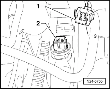
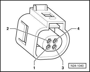
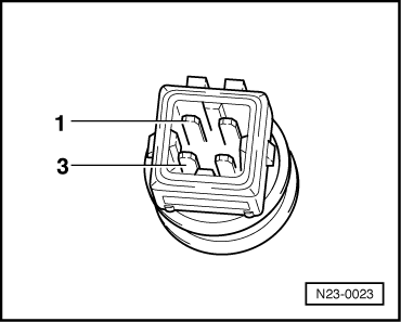
Note: Gradual introduction of coolant temperature sender with new connector and changed connector assignment. |
 |
|
Vehicles with old connector shape
Vehicles with new connector shape |
 |
|
Continuation for both connector shapes
|
 |
|
|
If no fault in wire is detected: Vehicles with old connector shape
|
 |
|
|
Vehicles with new connector shape
|
 |
|
|
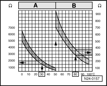
→ Scale A shows resistance values for temperature range 0...50 °C and scale B the values for temperature range 50...100 °C. Examples:
If the specification is not obtained: |