volkswagen Workshop Repair Guides

Volkswagen Workshop Service and Repair Manuals

Removing and installing camshaft oil seal > < Removing
Installing
Installing
  Note
t  
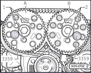
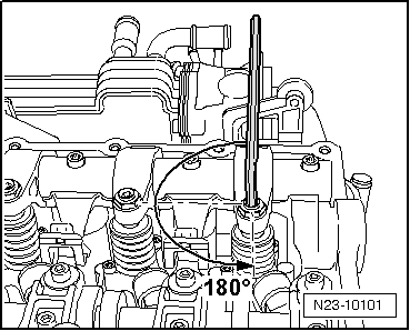
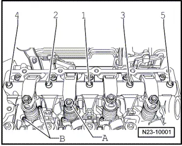
When camshafts are installed, cams for No. 1 cylinder must point upwards.
t  Do not interchange used bearing shells (mark).
t  
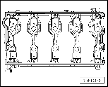
When installing camshafts, ensure proper seating of retaining lugs in retaining frame and cylinder head.
t  Seal parting surface between retaining frame and cylinder head using silicone adhesive sealant -D 176501 A1- → Fig.
t  
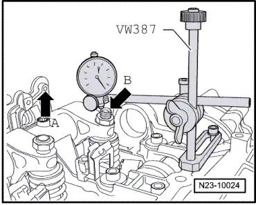
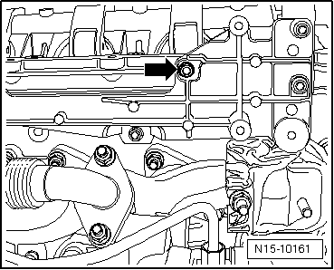
Each time work is performed which requires adjustment of the unit injector, the adjustment screw in the rocker arm and also the unit injector ball stud must be renewed.
   
Sealing parting surfaces of retaining frame
–  Oil running surfaces of shell bearings.
–  Install new ball studs into unit injectors.
–  Install retaining frame and rocker arm shaft.
  N15-10349
–  Evenly tighten bolts -1…20- as shown from inside to outside. Specified torque: 20 Nm
  N15-10001
–  Now tighten rocker arm shaft bolts -1…5-1/4 turn (90°) further.
–  Screw new adjustment screws into rocker arms hand-tight and fit lock nut.
–  Install camshaft oil seals → Chapter.
  Caution
Clean camshaft journal with a cloth and degreasing agent before fitting i.e. brake cleaner. An oiled camshaft journal reduces the friction between components when bolting on. This can cause items to expand and eventually lead to the hub shearing.
–  Set hubs on camshafts.
  N23-10001
–  Tighten securing bolts -1- for hubs. Torque specification: 100 Nm.
–  To do this, use counterhold -T10051-.
  N15-10043
–  Push camshaft pulleys onto hubs.
  Note
The toothed segment -arrow- of the camshaft toothed belt pulley must be on top.
–  Hand tighten securing bolts -1- and -2- on camshaft pulleys so that there is no play.
  N15-0275
–  Lock hubs using locking pin for diesel injection pump -3359-.
–  Install toothed belt and adjust valve timing → Chapter.
  N15-0702
–  Fit dial gauge onto adjustment screw of unit injector as shown.
–  Turn the crankshaft in engine direction of rotation until the roller of the rocker arm is positioned on the peak of the drive cam. Roller side -arrow A- positioned at highest point. Dial gauge -arrow B- positioned at lowest point.
–  Remove dial gauge.
–  Now turn adjustment screw into rocker arm until a firm resistance is felt (unit injector positioned at stop).
  N23-10024
–  Turn adjustment screw 180° back off stop.
–  Hold adjuster screw in this position and tighten lock nut to 30 Nm.
  N23-10101
–  Tighten upper securing bolt -arrow- of bracket for bypass flap and exhaust gas recirculation cooler to 10 Nm.
–  Install tandem pump → Chapter.
–  Install cylinder head cover → Chapter.
  Note
When new rocker fingers have been installed, engine must not be started for about 30 minutes. Hydraulic compensation elements must settle (otherwise valves will strike pistons).
  N15-10161

Removing and installing camshaft oil seal > < Removing