volkswagen Workshop Repair Guides

Volkswagen Workshop Service and Repair Manuals

Removing and installing vacuum unit for turbocharger > < Removing and installing turbocharger
Checking vacuum unit for turbocharger
Removing and installing vacuum unit for turbocharger → Chapter.
Adjusting vacuum unit for turbocharger → Chapter.
Special tools and workshop equipment required
   
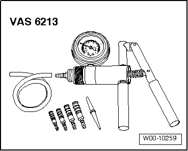
t  Hand vacuum pump -VAS 6213-
Test prerequisites
t  The hose from the turbocharger via the charge pressure control solenoid valve -N75- to the vacuum unit must have through-flow and be free of leaks.
t  Charge pressure control solenoid valve -N75- OK.
Procedure
  W00-10259
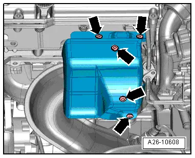
–  Unscrew bolts -arrows- and remove heat shield for turbocharger.
  A26-10608
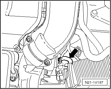
–  Pull hose -arrow- off vacuum unit.
  N21-10187
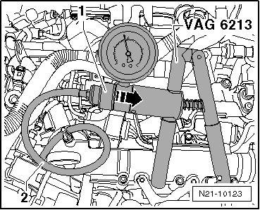
–  Place hose -2- of hand-operated vacuum pump -VAS 6213- onto vacuum unit connection.
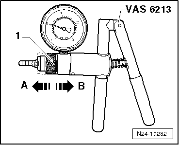
–  Push sliding ring -1- on hand vacuum pump -VAS 6213- to stop in direction of -arrow-.
–  Operate hand vacuum pump -VAS 6213- repeatedly.
  Caution
Excessive pressure may damage the vacuum unit.
The pressure must not exceed 800 mbar!
  Note
The illustration shows the installation position with the turbocharger removed.
  N21-10123
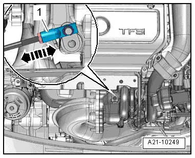
–  Observe operating rod -1- of turbocharger vacuum unit.
t  The operating rod must move from approx. 300 mbar.
t  At approx. 800 mbar, the operating rod must reach the end of the adjustment travel.
  A21-10249
–  Vent hand-operated vacuum pump -VAS 6213--arrow A-.
t  The operating rod must move in the opposite direction.
  Note
Check the movement sequence of the operating rod in the entire adjustment range. It must move continuously and smoothly.
Assembly is performed in the reverse order of removal.
Specified torque of heat shield for turbocharger: 8 Nm
  N24-10282

Removing and installing vacuum unit for turbocharger > < Removing and installing turbocharger