volkswagen Workshop Repair Guides

Volkswagen Workshop Service and Repair Manuals

Adjusting vacuum unit for turbocharger > < Checking vacuum unit for turbocharger
Removing and installing vacuum unit for turbocharger
Removing
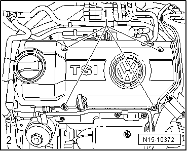
–  Detach coolant hose -2- from engine cover panel.
   
–  Pull oil dipstick out.
–  Unscrew bolts -arrows- and remove engine cover panel.
–  Remove air filter housing → Chapter.
  N15-10372
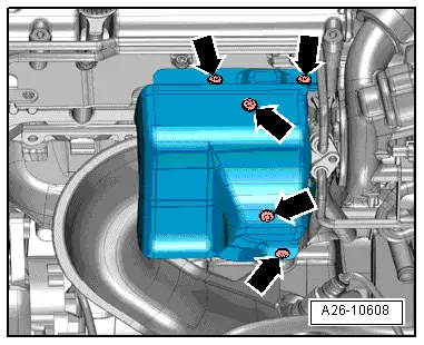
–  Unscrew bolts -arrows- and remove heat shield for turbocharger.
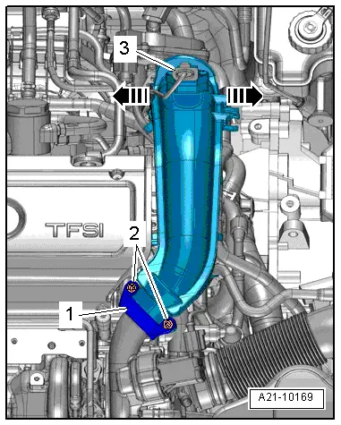
–  Unscrew bolts -2- and remove retaining clip -1-.
  A26-10608
–  Pull connector -3- off charge air pressure sender -G31-.
–  Release catches -arrows- and pull air pipe first off throttle valve module -J338- and then off turbocharger.
–  Lay hoses at air pipe to side.
  A21-10169
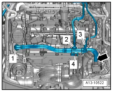
–  Unscrew bolt -4- and remove crankcase breather hose from turbocharger -arrow- and lay it to side.
  Note
The positions labelled -1, 2, 3- should be disregarded.
  A13-10522
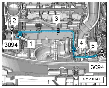
–  Clamp off coolant hoses using hose clips -3094- as illustrated.
–  Remove bolts -1, 3, 4, 5-.
–  Pull coolant lines off turbocharger and lay to side.
  Note
The position labelled -2- should be disregarded.
  A21-10242
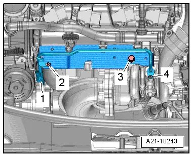
–  Unscrew bolts -2- and -3-, then remove retaining plate.
  Note
The positions labelled -1- and -4- should be disregarded.
  A21-10243
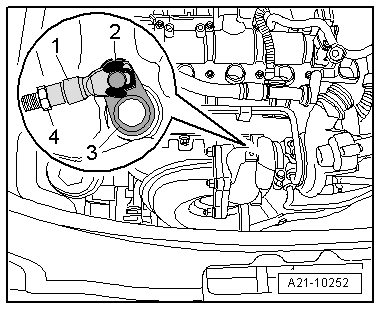
–  Lever off securing clip -2- and pull threaded piece -1- of operating rod off operating lever pin -3-.
  Note
The position labelled -4- should be disregarded.
  A21-10252
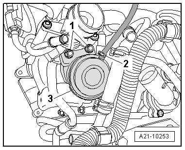
–  Remove hose -2- from turbocharger vacuum unit.
–  Unscrew bolts -1- and remove turbocharger vacuum unit -3-.
Installing
Specified torques → Chapter.
Specified torque of heat shield for turbocharger: 8 Nm
Installation is performed in the reverse order of removal.
–  Install new securing clip for operating rod.
  Note
Ensure securing clip seats correctly in the pin groove.
–  Adjusting vacuum unit for turbocharger → Chapter.
  A21-10253

Adjusting vacuum unit for turbocharger > < Checking vacuum unit for turbocharger