
Golf Mk5
| Adjusting vacuum unit for turbocharger |

| Special tools and workshop equipment required |
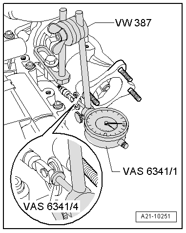
| t | Universal dial gauge bracket -VW 387- |
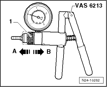
| t | Hand vacuum pump -VAS 6213- |
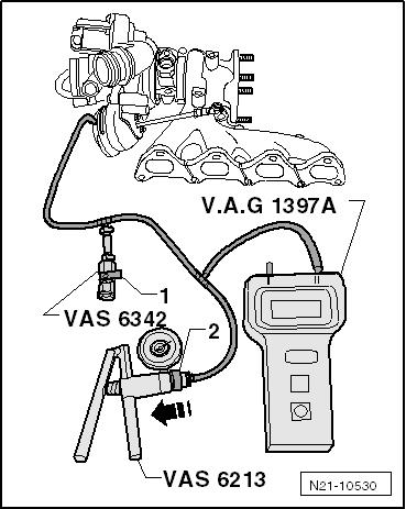
| t | Pressure regulating valve -VAS 6342- |
| t | Turbocharger tester -V.A.G 1397A- |
| t | Dial gauge set, 4-part -VAS 6341- |
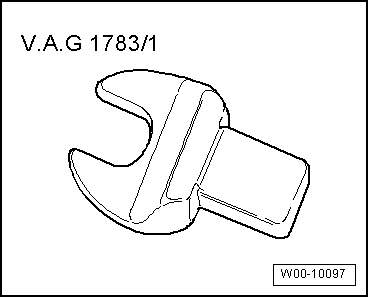
| t | Torque wrench -V.A.G 1783- |
|
|
|
|
|
|
|
|
|
|
 Note
Note
|
|
Note
|
|
Note
|
|
Note
|
|
|
|
 Caution
|
|
|
|
Note
|
|