| –
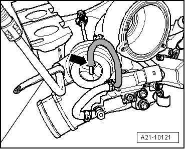
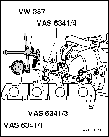
| Secure universal dial gauge bracket -VW 387- to turbocharger -arrows-. |
| –
| Secure dial gauge -VAS 6341/1- with dial gauge extension, 30 mm -VAS 6341/3- and flat pickup -VAS 6341/4- to universal dial gauge bracket -VW 387-. |
| –
| With pressure at 0 bar, set dial gauge -VAS 6341/1- to 1 mm preload. |
| –
| Turn dial of dial gauge -VAS 6341/1- to 0. |
| –
| Make sure that dial gauge can move freely. |
| –
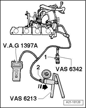
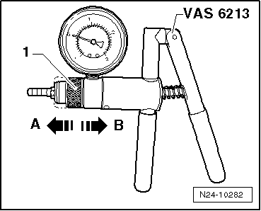
| Operate vacuum pump -VAS 6213- until turbocharger tester -V.A.G 1397A- indicates 350 +/- 5 mbar. |
| –
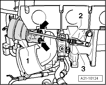
| The dial gauge must indicate 4.1 mm to 4.3 mm, otherwise turn rod of vacuum unit until the value is indicated. |
| –
| Tighten lock nut hand-tight. |

Note | The values in mm refer to the read value (includes 1 mm pretension). |
| –
| Vent system via pressure control valve -VAS 6342- so that pressure reading drops to 0 mbar. |
| –
| Set dial gauge -VAS 6341/1- to 0. |
Note | The following measurements must be performed in continuous sequence. Do not allow the pressure to drop to 0 between measurements. |
| –
| Operate vacuum pump -VAS 6213- until turbocharger tester -V.A.G 1397A- indicates 350 +/- 5 mbar. |
| –
| Read off and note value indicated on dial gauge -VAS 6341/1-. |
| –
| Operate vacuum pump -VAS 6213- until turbocharger tester -V.A.G 1397A- indicates a value between 650 mbar and 700 mbar. |
| –
| Vent system via pressure control valve -VAS 6342- so that pressure reading drops to 350 +/- 5 mbar. |
| –
| Read off and note value indicated on dial gauge -VAS 6341/1-. |
| –
| Add values 1 and 2 together and divide by 2. |
| –
| The result (mean value) should be 5 +/- 0.25 mm. |
| –
| Correct setting if the result (average) is not 5 +/- 0.25 mm, tighten lock nut hand-tight and repeat measurement. |
| –
| If the result (mean value) is 5 +/- 0.25 mm, tighten the lock nut to 5 Nm and secure with sealing paint. |
| –
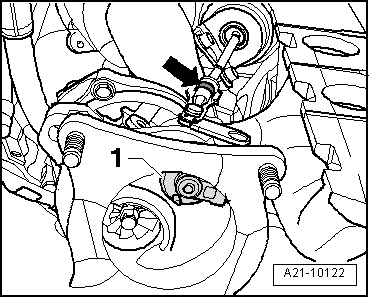
| Secure locking plate above turbocharger linkage. |
|
|
|