volkswagen Workshop Repair Guides

Volkswagen Workshop Service and Repair Manuals

Checking vacuum unit for turbocharger > < Part III
Removing and installing turbocharger
Special tools and workshop equipment required
   
t  Spring-type clip pliers -VAS 5024 A-
  W00-1179
t  Tensioning strap -T10038-
  Caution
When a mechanical fault is found on the turbocharger, e.g. a destroyed compressor impeller, it is not only sufficient to renew the turbocharger. To prevent this from causing further damage, perform the following repairs:
t  Check air filter housing, air filter element and intake hoses for soiling.
t  Check complete charged air routing and charge air cooler for foreign objects.
If foreign objects are found in the charge air system, the charged air routing must be cleaned and the charge air cooler must be renewed, if necessary.
Removing:
–  Remove engine cover/air filter → Chapter and remove intake hose → Item from turbocharger.
–  Drain coolant → Chapter.
  W00-1005
–  Remove right front part of wheel housing liner.
  A10-1643
–  Pull charge air hose -arrow- off charge air cooler.
  A21-10050
–  Unscrew bolts -arrows- and remove charge air pipe.
  A21-10030
–  Pull off connectors -1 and 2- and unclip wire.
–  Unscrew bolts -arrows- and remove union from turbocharger.
  N21-10043
–  Disconnect connector for Lambda probe -G39--arrow- and lay cable to side.
  A26-10134
–  Pull connectors off ignition coils and lay wiring harness to side.
  N28-10010
–  Disconnect coolant line to coolant expansion tank -arrow-.
  A21-10043
–  Pull off coolant hoses -1- and -2-.
–  Disconnect coolant line -3-.
  A21-10042
–  Pull upper coolant hose off heat exchanger -arrows-.
  N21-10045
–  Remove heat shield and coolant pipe -arrows-.
  N21-10044
–  Unbolt crankcase breather line with heat shield from turbocharger -1-.
–  Disconnect crankcase breather line from cylinder head cover -2- and remove.
–  Remove activated charcoal filter line to turbocharger from cylinder head cover -3-.
–  Loosen turbocharger oil supply line -4-.
  A21-10032
–  Remove the two upper securing nuts for front exhaust pipe/turbocharger.
  N26-10097
–  Unbolt heat shield for right-hand drive shaft -arrows-.
  A10-1633
–  Remove the two lower securing nuts for front exhaust pipe/turbocharger.
  N26-10097
–  Unbolt bracket for exhaust system -arrows-.
  A10-1632
–  Separate exhaust system at clamp -arrows-.
–  Pull front exhaust pipe off turbocharger and slightly push to rear.
  Note
The catalytic converter is not removed and the Lambda probe connector is not separated.
  A10-1734
–  Unbolt oil supply line and coolant supply line from turbocharger -arrows-.
  N15-10166
–  Remove oil return line -arrows- at turbocharger.
  A21-10048
–  Remove bolts -1- and -2- and remove support for turbocharger.
  Note
The following procedure is necessary to provide more space between the cylinder head and bulkhead.
  A21-10047
–  Remove bolts -2 and 3-.
  A10-1578
–  Pull engine approx. 20 mm to rear using tensioning strap -T10038-.
  N21-10042
–  Disconnect coolant pipe -arrow-.
  Note
t  The clamping strip nuts need not be loosened.
t  Bolt -1- is only fitted on coolant pipes with two retainers.
  A21-10036
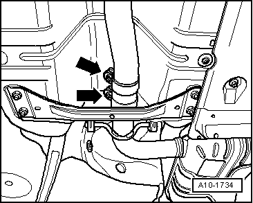
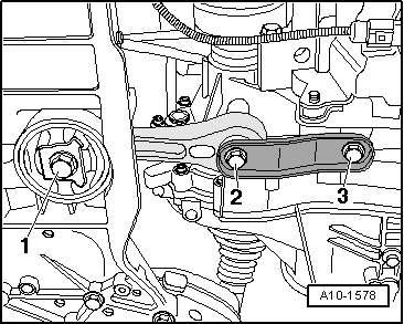
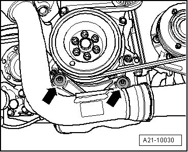
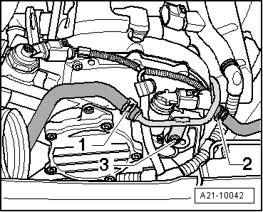
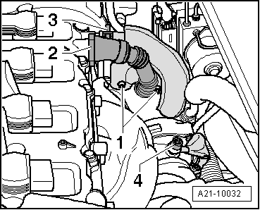
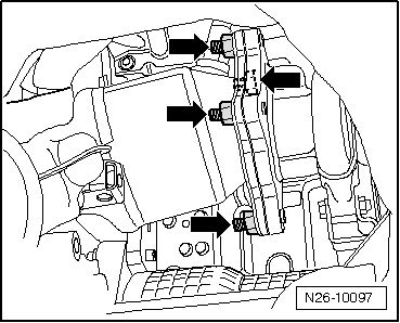
–  Unscrew bolt -1- for coolant pipe and remove upper nuts -arrows-.
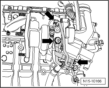
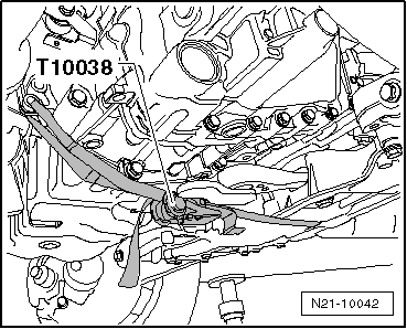
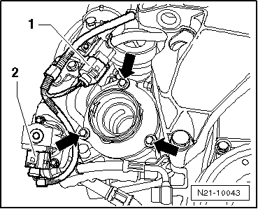
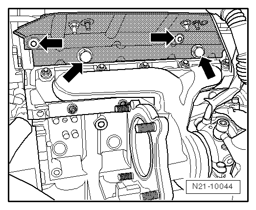
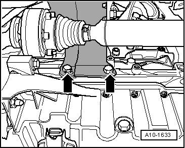
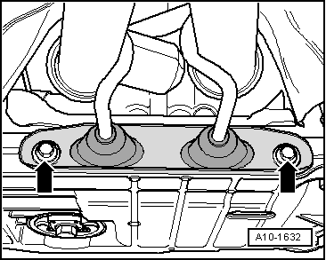
–  Remove turbocharger/exhaust manifold upwards.
Installing:
  Caution
When a mechanical fault is found on the turbocharger, e.g. a destroyed compressor impeller, it is not only sufficient to renew the turbocharger. To prevent this from causing further damage, perform the following repairs:
t  Check air filter housing, air filter element and intake hoses for soiling.
t  Check complete charged air routing and charge air cooler for foreign objects.
If foreign objects are found in the charge air system, the charged air routing must be cleaned and the charge air cooler must be renewed, if necessary.
Installation is carried out in the reverse order. When installing, note the following:
t  Fitting hose connections with plug-in connectors → Chapter
t  Renew seals, gaskets and self-locking nuts.
t  Fill turbocharger with engine oil at oil supply line connection.
t  
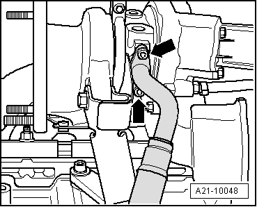
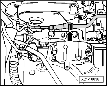
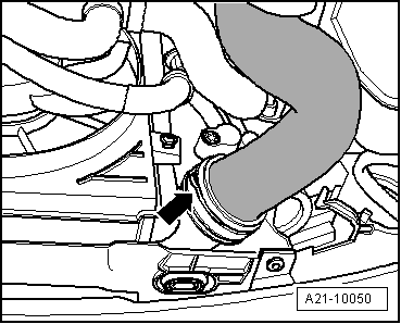
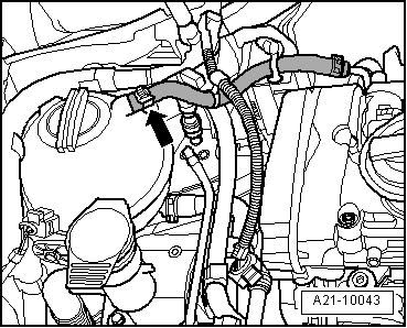
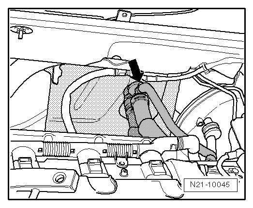
The coolant return line → Item must be installed together with the turbocharger.
t  Hose connections and hoses for charge air system must be free of oil and grease before assembly. The oil seals and sealing surfaces must be oiled lightly only for connector couplings → Chapter.
t  
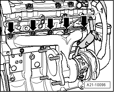
Secure all hose connections with hose clips which conform to production standard.
t  After installing turbocharger, run engine for about 1 minute at idling speed to ensure that oil is supplied to turbocharger.
Specified torques → Chapter.
  A21-10096
Component Nm
Pendulum support to gearbox → Fig.
Exhaust manifold/turbocharger to cylinder head201)
Oil supply line to turbocharger30
Oil return line to turbocharger9
Coolant supply line to turbocharger35
Turbocharger bracket to cylinder block302)
Turbocharger bracket to turbocharger302)
Air intake pipe (right side) to sump10

1) Renew nuts.
2) Use high-temperature paste → ETKA (Electronic Parts Catalogue).
   

Checking vacuum unit for turbocharger > < Part III