
Golf Mk5
| Part I: Assembly overview - chain drive |

| 1 - | Valve timing housing |
| q | Markings on valve timing housing → Fig. |
| q | Lightly lubricate contact surfaces of oil seals before installing. |
| q | Removing and installing → Chapter |
| q | Dismantling and assembling → Fig.. |
| q | Before installing valve timing housing, check strainer for soiling → Fig.. |
| 2 - | 8 Nm |
| q | Insert with locking fluid -D 000 600 A2- |
| 3 - | Camshaft timing chain |
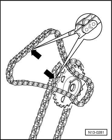
| q | Before removing, mark direction of rotation (installation position) → Fig.. |
| q | Installing → Chapter |
| 4 - | Exhaust camshaft adjuster |
| q | Identification: 32A. |
| q | Rotate engine only with camshaft adjuster installed. |
| q | Installing → Chapter |
| 5 - | Intermediate shaft |
| 6 - | Tensioning plate |
| q | For camshaft timing chain → Item |
| 7 - | Pivot pin, 18 Nm |
| 8 - | Chain tensioner, 40 Nm |
| q | For camshaft timing chain → Item |
| q | Only rotate engine when chain tensioner is installed. |
| 9 - | Seal |
| q | Renew if damaged or leaking. |
| 10 - | Chain sprocket |
| q | For intermediate shaft drive chain → Item |
| q | Installing → Chapter |
| 11 - | Chain sprocket |
| q | For camshaft timing chain → Item |
| q | Installing → Chapter |
| 12 - | 60 Nm + 1/4 turn (90°) further |
| q | Renew. |
| q | To tighten and loosen, use counterhold -T10069- → Chapter |
| 13 - | Chain tensioner with tensioning plate |
| q | For intermediate shaft drive chain → Item |
| q | Before installing, release locking splines in chain tensioner using a small screwdriver and press tensioning plate against chain tensioner. |
| q | Only rotate engine when chain tensioner is installed. |
| 14 - | Drive sprocket |
| q | Built into crankshaft. |
| q | Ground down tooth aligned with main bearing joint = TDC No. 1 cylinder → Chapter |
| 15 - | Drive chain for intermediate shaft |
| q | Before removing, mark direction of rotation (installation position) → Fig.. |
| q | Installing → Chapter |
| 16 - | Guide rail |
| q | Remove and install together with intermediate shaft drive chain → Chapter |
| 17 - | Locating pin without collar, 10 Nm |
| q | For guide rail → Item. |
| 18 - | 18 Nm |
| 19 - | 23 Nm |
| 20 - | Inlet camshaft adjuster |
| q | Identification: 24E |
| q | Rotate engine only with camshaft adjuster installed. |
| q | Installing → Chapter |
| 21 - | 60 Nm + 1/4 turn (90°) further |
| q | Renew. |
| q | Contact surface of sender wheel must be dry around bolt head when installed. |
| q | To remove and install, counterhold with 32 mm open-end spanner on camshaft → Chapter |
| 22 - | Guide rail |
| q | For camshaft timing chain → Item |
| 23 - | Exhaust camshaft control valve 1 -N318- |
| q | For exhaust camshaft. |
| q | Removing and installing → Chapter |
| q | Before removing, mark connector belonging to component. |
| 24 - | Inlet camshaft control valve 1 -N205- |
| q | For inlet camshaft. |
| q | Removing and installing → Chapter |
| q | Before removing, mark connector belonging to component. |
| 25 - | Guide rail |
| q | For camshaft timing chain |
| q | Clipped into valve timing housing. |
 Note
Note
|
|