volkswagen Workshop Repair Guides

Volkswagen Workshop Service and Repair Manuals

Exhaust system > < Removing and installing engine control unit
Removing and installing anti-theft engine control unit
Special tools and workshop equipment required
t  Saw set -V.A.G 1561/14-
t  Grip pliers
   
t  Electric cutter -V.A.G 1561 A-
  W00-0532
t  
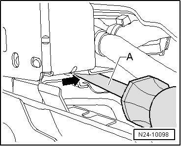
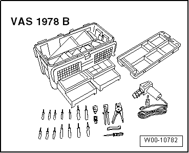
Hot air blower from wiring harness repair set -VAS 1978 B-
t  Small nozzle attachment from wiring harness repair set -VAS 1978 B-
  Note
If the engine control unit is to be renewed, connect Vehicle diagnosis, testing and information system -VAS 5051B- and perform „Renewing engine control unit“ in guided functions.
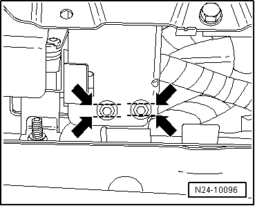
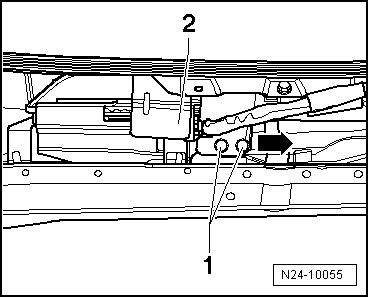
Removing
–  Switch off ignition.
–  Remove wiper arms, plenum chamber cover and plenum chamber bulkhead: → Electrical system; Rep. gr.92.
  Note
The shear-head bolt threads are coated with locking compound. Heating the shear-head bolt with a hot air blower releases the locking effect of the locking compound.
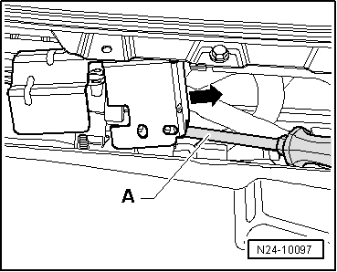
  Caution
Cover lines, connections and control units in the vicinity of the engine control unit to prevent damage through heat (scorching/melting of plastics etc.).
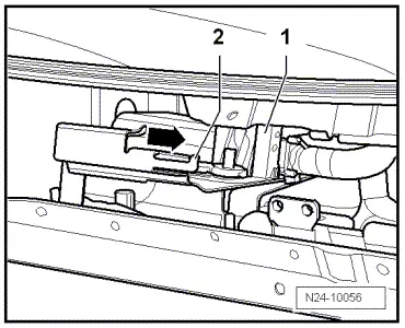
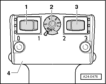
Perform settings on hot air blower -4- as shown:
  W00-10782
–  Turn temperature setting potentiometer -2- to maximum heat output (600 °C).
–  Set two-stage switch for volume of air -3- to position 3.
  WARNING
When shear-head bolts are heated up, parts of the protective housing will be subjected to a large amount of heat. Wear protective gloves to avoid possible injury.
–  Place nozzle of hot air blower close to shear-head bolt.
–  Switch on hot air blower and heat the bolts.
–  Remove bolts with grip pliers.
  Note
  A24-0476
If the bolts will not move, saw into heads of shear-head bolts so that two parallel slots are created -arrows- and then remove the bolts.
  N24-10096
–  Insert a screwdriver between protective housing -A- and bracket -arrow-.
  N24-10098
–  Lever up protective housing using screwdriver -A- and in sideward motion pull off bracket -arrow-.
  N24-10097
–  Release front connector -1- from engine control unit and pull it off.
–  Lever up catch -2- slightly.
–  Then push engine control unit out of retainer -arrow-.
–  Then release rear connector on engine control unit and pull it off.
Installing
–  Fit rear connector to engine control unit and lock in position.
–  Push engine control unit onto bracket.
–  Fit front connector to engine control unit and lock it in position.
–  Push protective housing onto bracket.
  N24-10056
–  Tighten new shear-head bolts -1- evenly until heads shear-head off.
–  Install plenum chamber bulkhead, plenum chamber cover and wiper arms → Electrical system; Rep. gr.92.
  N24-10055

Exhaust system > < Removing and installing engine control unit