
Golf Mk6
| Removing and installing camshaft |

| Special tools and workshop equipment required |
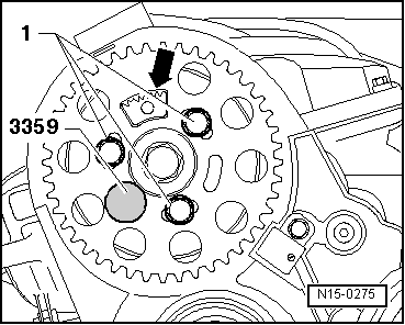
| t | Diesel injection pump locking pin -3359- |
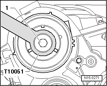
| t | Counterhold tool -T10051- |
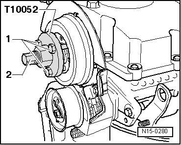
| t | Puller -T10052- |
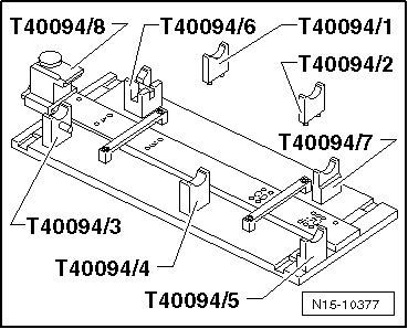
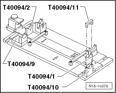
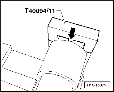
| t | Camshaft fitting tool -T40094- |
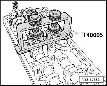
| t | Camshaft clamping tool -T40095- |
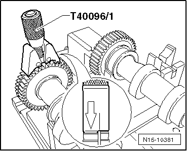
| t | Camshaft fitting tool -T40096- |
|
|
|
|
|
|
|
|
|
|
 Note
Note
|
|
Note
|
|
 Caution
Note
|
|
|
|
|
|
|
|
|
|
|
|
|
|
|
|
|
|
|
|
Note
|
|