volkswagen Workshop Repair Guides

Volkswagen Workshop Service and Repair Manuals

Inlet and exhaust valves > < Removing and installing camshaft
Removing and installing valve stem seals
   
Removing and installing valve stem seals
Special tools and workshop equipment required
t  10 mm jointed spanner -3220-
t  Valve stem seal puller -3364-
t  Valve stem seal fitting tool -3365-
t  Removal and installation device for valve cotters -VAS 5161- with guide plate -VAS 5161/23- and knurled spacer ring -VAS 5161/23-1-

Procedure
–  Remove all glow plugs using U/J extension and socket -3220- → Chapter.
–  Remove camshafts → Chapter.
–  Fit guide plate -VAS 5161/23- onto cylinder head.
   
–  Secure guide plate on intake manifold side with knurled screw -VAS 5161/12- and tighten it hand-tight to studs using M6 collarless nuts -1-.
–  Screw sealing pin -VAS 5161/10- into guide plate.
  N15-10450
–  Screw adapter -VAS 5161/11- hand-tight into glow plug hole of relevant cylinder.
  N15-10451
–  Insert drift -VAS 5161/3- into guide plate and knock valve cotters loose using a plastic hammer.
  N15-10452
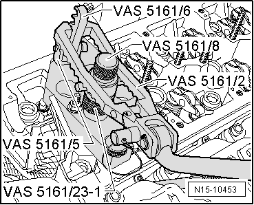
–  Screw engaging fork -VAS 5161/5- with snap-in device -VAS 5161/6- into guide plate.
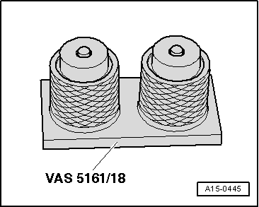
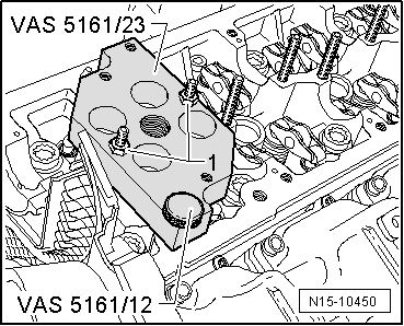
–  Slide knurled spacer ring -VAS 5161/23-1- onto assembly cartridge -VAS 5161/8-.
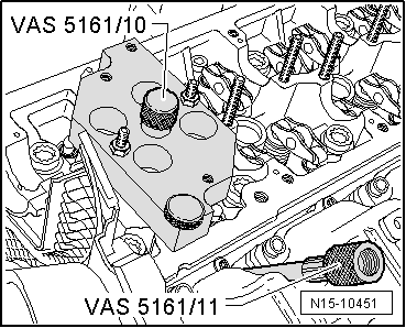
–  Connect adapter -VAS 5161/11- to compressed air line using a commercially available connection piece, and apply constant air pressure.
l  Minimum pressure: 6 bar
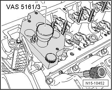
–  Attach pressure fork -VAS 5161/2- to snap-in device and push assembly cartridge down.
–  At the same time, turn knurled screw of assembly cartridge clockwise until tips engage in valve cotters.
–  Move knurled screw back and forth lightly to press apart valve cotters and capture them in the assembly piece.
–  Release pressure fork.
–  Take out assembly cartridge with knurled spacer ring, valve plate and valve spring.
  N15-10453
–  Remove valve stem oil seals using valve stem seal puller -3364-.
  Note
  N15-10537
A plastic sleeve -A- is included with the new valve stem oil seals.
–  Fit plastic sleeve -A- onto valve stem to prevent damage to new valve stem oil seal -B-.
–  Lightly lubricate sealing lip of valve stem oil seal.
–  Slip valve stem oil seal over plastic sleeve.
–  Carefully press valve stem oil seal onto valve guide using valve stem seal fitting tool -3365-.
–  If necessary, use a plastic head hammer and tap lightly on fitting tool until valve stem oil seal is fitted to stop.
–  Remove plastic sleeve.
–  Insert valve spring and valve spring plate into cylinder head.
  A15-0282
–  If valve cotters have been removed from assembly cartridge, they need to be put into insertion device -VAS 5161/18- first.
  Note
Larger diameter of valve cotters faces upwards.
–  Press assembly cartridge onto insertion device from above and pick up valve cotters.
  A15-0445
–  Re-insert assembly cartridge -VAS 5161/8- into guide plate.
–  Push pressure fork down and pull knurled screw upwards while turning to left and right - this will insert the valve cotters.
–  Release pressure fork with knurled screw still in pulled position.
Installation is carried out in the reverse order; note the following:
–  Install glow plugs → Chapter.
–  Install camshafts → Chapter.
  Note
t  Engine is not to be rotated for approx. 30 minutes after installing camshafts. The hydraulic compensation elements must settle (otherwise valves will strike pistons).
t  After working on the valve gear, turn the engine carefully at least 2 rotations to ensure that none of the valves make contact when the starter is operated.
  N15-10453

Inlet and exhaust valves > < Removing and installing camshaft