volkswagen Workshop Repair Guides

Volkswagen Workshop Service and Repair Manuals

Removing and installing cylinder head > < Removing and installing camshaft
Fitting the cylinder head cover
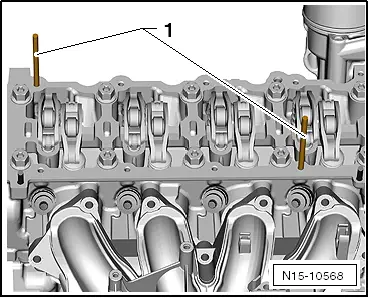
  Caution
The studs (M6x70) must be screwed into cylinder head before cylinder head cover is installed.
The cylinder head cover is guided by the studs, so that the roller rocker fingers do not slip off the supporting elements.
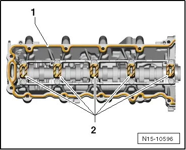
–  Remove sealant residues from cylinder head and cylinder head cover with a rotating brush, e.g. a hand drill with a plastic brush (wear eye protection).
–  Clean sealing surfaces carefully. They must be free of oil and grease.
–  Also prevent dirt and residual sealant from entering cylinder head.
Prerequisite
l  
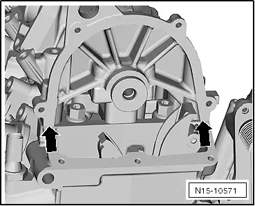
The pistons must not be positioned at TDC.
   
–  Screw two studs (M6x70) -1- into cylinder head before putting on cylinder head cover.
  Caution
Cylinder head cover is sealed using 2 different sealants!
  Note
Sealant must not be applied too thickly; otherwise excess sealant can enter oil channels and cause damage to engine.
–  Clean sealing surfaces carefully. They must be free of oil and grease.
–  Apply sealant D 189 500 A1 to sealing surface -1-.
  N15-10568
Bead of sealant must be 2 … 3 mm thick and must run closer to inside edge in area of bolt holes.
–  Apply the sealant D 154 103 A1 thinly and evenly onto the sealing surfaces -2- indicated by diagonal lines.
–  Check that roller rocker fingers are in contact with support elements.
–  Carefully place cylinder head cover over studs and dowel pins onto cylinder head.
  N15-10596
–  Tighten new securing bolts in cylinder head cover in specified sequence -A- to -J-.
Specified torque: 8 Nm + turn 90° further.
  Caution
It is essential to remove sealant for cylinder head cover in area of -arrows-.
In order to avoid leaks, do not mix together both sealants for cylinder head cover and for valve timing housing.
  N15-10570
–  Remove surplus sealant in area of -arrows-.
–  Turn crankshaft in normal direction of rotation until the stop.
  N15-10571
–  Raise timing chain using assembly tool -T10118-.
  Caution
Sump only needs to be removed on vehicles ► 12.2009.
In these vehicles, the timing chain can slip off the crankshaft chain sprocket during installation!
  N15-10554
–  From underneath, check timing chain -1- is in correct position on crankshaft chain sprocket.
All vehicles
  N15-10557
–  Place timing chain -1- onto chain sprocket -2-.
Timing chain must make contact in area of guide rail -3- and be slightly tensioned.
–  Tighten new securing bolt by hand.
Timing chain must be guided centrally onto tensioning rail.
  N15-10555
–  Tighten chain tensioner to 60 Nm.
  N15-10550
–  Fit a new securing bolt and tighten camshaft chain sprocket -1- to 50 Nm.
  Note
Securing bolt is not tightened by a 1/4 turn (90°) further until after timings have been checked at end of procedure.
–  When doing this, hold camshaft chain sprocket with counterhold tool -T10172-.
–  Remove locking pin -T10414- from camshaft.
–  Unscrew locking pin -T10340- from cylinder block.
–  Turn crankshaft 2 revolutions in normal direction of rotation.
–  Screw locking pin -T10340- to stop into crankcase.
–  Turn crankshaft in normal direction of rotation until the stop.
Timing is OK if locking pin -T10414- can be pushed into camshaft.
If control times are not OK
–  Repeat valve timing adjustment.
  N15-10551
–  Turn securing bolt a -1-1/4 turn (90°) further.
–  When doing this, hold camshaft chain sprocket with counterhold tool -T10172-.
–  Remove locking pin -T10414- and locking pin -T10340-.
t  Install control housing (top) → Chapter.
t  Install turbocharger → Chapter.
t  Install sump (only for vehicles ► 12.2009) → Chapter.
t  Install crankshaft pulley → Chapter.
t  Install high-pressure pump → Chapter.
t  Attach fuel lines → Chapter.
t  Further assembly is basically the reverse of the dismantling sequence.
  N15-10551

Removing and installing cylinder head > < Removing and installing camshaft