
Golf Mk6
| Removing and installing cylinder head |
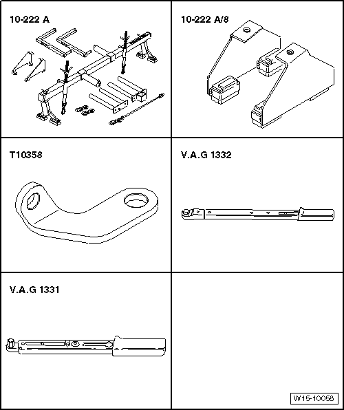
| Special tools and workshop equipment required |
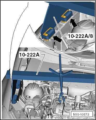
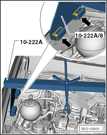
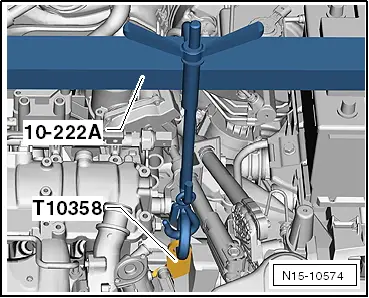
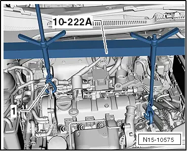
| t | Support bracket -10 - 222 A- |
| t | Adapter -10 - 222 A /8- |
| t | Bracket -T10358- |
| t | Torque wrench (40 … 200 Nm) -V.A.G 1332- |
| t | Torque wrench (5 … 50 Nm) -V.A.G 1331- |
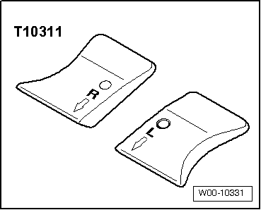
| t | Wing compensation plate -T10311- (Golf Plus only) |
|
|
 WARNING
|
|
|
|
|
|
|
|
|
|
|
|
|
|
 Caution
|
|
|
|
|
|
 Note
Note
|
|
|
|