
Golf Mk6
| Schematic diagram of activated charcoal filter system (engine codes CBFA, CCTA) |
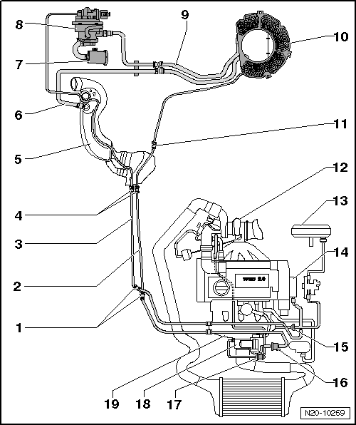
| 1 - | Separating point |
| q | Front right in engine compartment under coolant expansion tank |
| 2 - | Breather line |
| q | White |
| q | From activated charcoal filter to activated charcoal filter solenoid valve 1 -N80- |
| q | Installation position: On right under vehicle |
| q | Secured to fuel tank. |
| 3 - | Breather line |
| q | Green |
| q | From engine to fuel system diagnosis pump -V144- |
| q | Installation position: On right under vehicle |
| q | Secured to fuel tank. |
| 4 - | Separating point |
| q | Front right on fuel tank in vicinity of fuel filter |
| 5 - | Filler neck |
| 6 - | Breather line |
| q | From filler neck to activated charcoal filter |
| 7 - | Air filter |
| q | For fuel system diagnostic pump -V144- |
| 8 - | Fuel system diagnostic pump -V144- |
| q | Fitting location: In rear right wheel housing beneath liner |
| q | Removing and installing → Chapter. |
| q | Checking fuel system for leaks → Chapter |
| 9 - | Connecting line |
| q | From fuel system diagnosis pump -V144- to activated charcoal filter |
| q | Clip onto bracket. |
| 10 - | Activated charcoal filter |
| q | Location: down in spare wheel well |
| q | Removing and installing → Chapter. |
| 11 - | Separating point |
| q | Rear right on fuel tank |
| 12 - | Turbocharger |
| 13 - | Brake servo |
| 14 - | Vacuum pump |
| 15 - | Non-return valve |
| q | Location: Arrow points in direction of flow |
| 16 - | Activated charcoal filter solenoid valve 1 -N80- |
| q | Checking → vehicle diagnosis tester. |
| 17 - | Dual non-return valve |
| q | Testing → Fuel preparation, injection; Rep. gr.24 |
| 18 - | Throttle valve module -J338- |
| q | Removing and installing → Fuel preparation, injection; Rep. gr.24 |
| 19 - | Intake manifold |