
Passat (B3)
|
Removing and installing gearbox
Removing and installing gearbox - Vehicles with 4 cylinder engine -
Removing
Note: Note radio coding for vehicles with coded radio. On vehicles with G charger:
=> Repair group 21; Removing and installing parts of exhaust system |
 |
|
On vehicles with electronic speedometer:
|
 |
|
|
 |
|
|
 |
|
Note: Do not depress clutch pedal. On vehicles with mechanical speedometer:
|
 |
|
|
 |
|
|
 |
|
|
 |
|
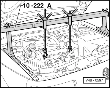
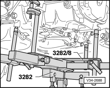
Attention!
The legs 10-222 A/1 are designed for the inclination of the bodywork. When the earlier type legs are used, there is a chance of accident!
|
 |
|
=> Repair group 27; Removing and installing starter.
|
 |
|
=> Repair group 26; Removing and installing parts of exhaust system.
|
 |
|
|
 |
|
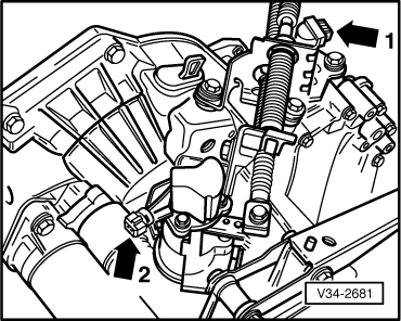
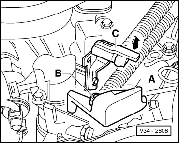
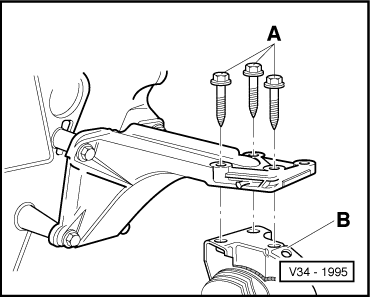
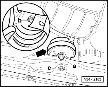
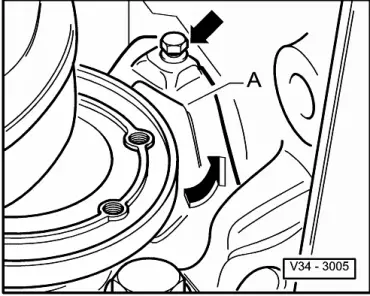
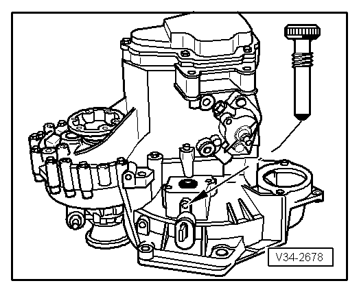
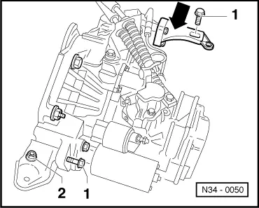
To do this remove gearbox console securing bolt -B- as follows:
Note: Do not damage P.A.S. pipe when moving engine/gearbox assembly. |
 |
|
|
 |
|
|
On vehicles with 4 valve engine:
|
 |
|
Note: Do not damage P.A.S pipe.
|
 |
|
 |
|
Note: Do not damage P.A.S pipe when lowering gearbox. |
 |
|
|
 |
|
|
Notes:
|
 |
|
|
|
|
=> Running gear; Repair group 40; Servicing drive shaft
=> Repair group 27; Removing and installing starter.
Tightening torques |
 |
|||||||||||||||||||||||||
|
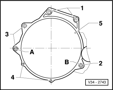
→ Gearbox to engine
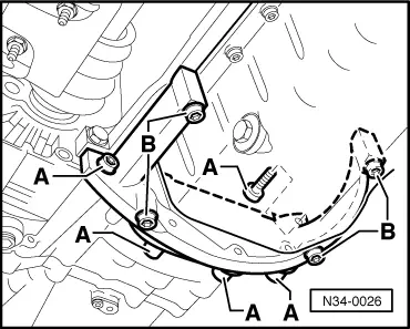
1) Also starter to gearbox 2) Flywheel large cover plate (not on vehicles with 4 valve engine) 3) Flywheel small cover plate Pos. A + B - Dowel sleeves |
 |
|||||||||||||||||||||||
|
→ Assembly mountings
| |||||||||||||||||||||||
|
|||||||||
|
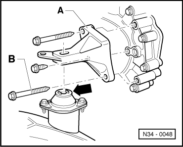
→ Front engine mounting to:
| |||||||||
|
||||||||||||||||||
| ||||||||||||||||||