
Passat (B3)
|
Removing and installing gearbox
Removing and installing gearbox - Vehicles with 6 cylinder fuel injection engine -
Removing
Note: For vehicles with coded radio obtain radio code. |
 |
|
|
 |
|
|
 |
|
|
 |
|
|
 |
|
|
 |
|
|
 |
|
|
 |
|
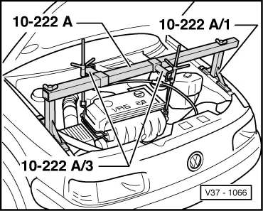
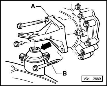
Note: Before fitting the support hooks of the support bar, remove hose and wire connections from engine in the area of the lifting eyes, so that they are not damaged.
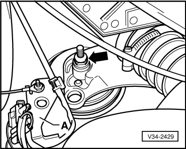
=> Repair group 27; Removing and installing starter. Note: Before removing the lower starter securing bolt remove P.A.S. pipe retainer from gearbox.
|
 |
|
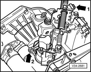
=> Repair group 26; Removing and installing parts of the exhaust system.
|
 |
|
|
 |
|
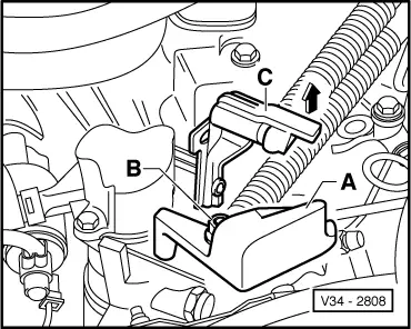
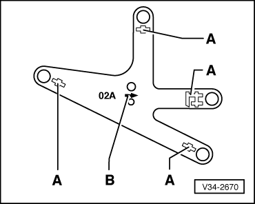
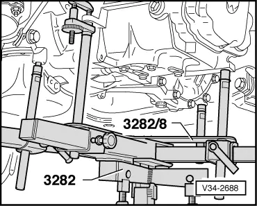
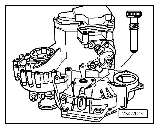
Note: Adjustment plate only fits in one position. |
 |
|
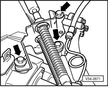
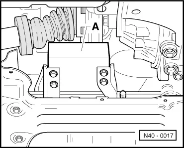
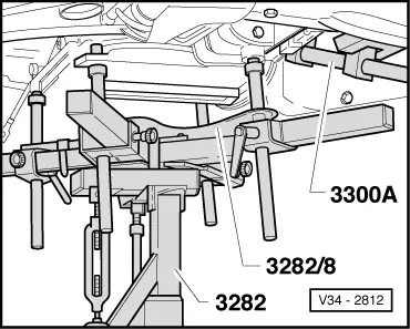
Note: Gearbox cover must lightly contact left-hand longitudinal member. |
 |
|
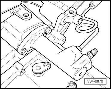
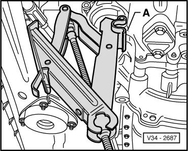
Note: When lowering do not damage the P.A.S pipe. |
 |
|
|
 |
|
=> Repair group 10; removing and installing engine. Notes:
|
 |
|
Tightening torques |
 |
|||||||||||||||||||||||||||||
|
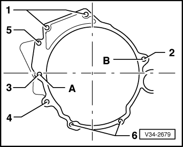
→ Gearbox to engine
1)Also front console to gearbox 2)Also starter and front console to gearbox
3)Flywheel cover plate |
 |
|||||||||||||||||||
|
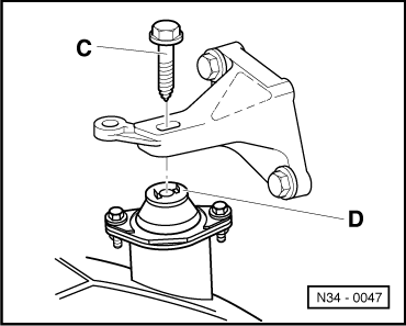
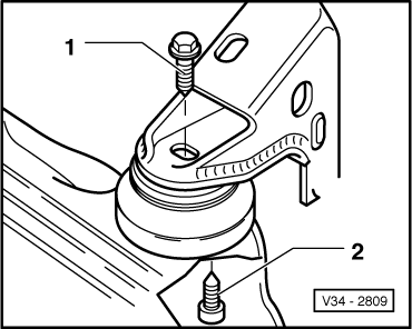
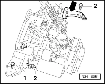
→ Assembly mountings
| |||||||||||||||||||
|
|||||||||||||||
| |||||||||||||||