volkswagen Workshop Repair Guides

Volkswagen Workshop Service and Repair Manuals

Adjusting output shaft > < Carrying out check measurement
5-Speed manual gearbox 02A
Dismantling and assembling output shaft (pinion shaft)
 
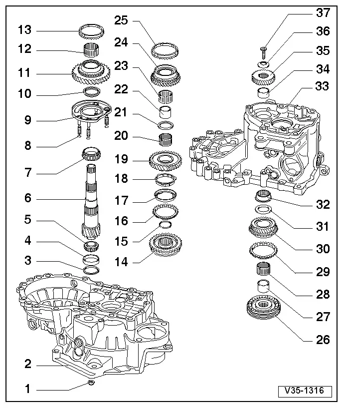
V35-1316

Notes:

  • ◆ The output shaft is dismantled as follows:
    - Position separating device under 2nd gear wheel (item19 ) and press off as described in Fig. 5.
    - Remove circlip (item15 ).
    - Position two-arm puller under bearing support (item 9 ) and pull off locking collar with 1st and 2nd gear synchro-hub as described in Fig.6 .
  • ◆ When installing new gear wheels or a new output shaft consult technical data
    .
 
V35-1316
  • ◆ Removing and installing output shaft
    .
  • ◆ Both taper roller bearings must be renewed together as a set.
  • Hexagon nut, 25 Nm and then turn 90°further
    • ◆ 4 nuts for bearing support
  • Clutch housing
  • Shim
    • ◆ Determining thickness - adjusting output shaft => Page 35-43
  • Small taper roller bearing outer race
    • ◆ Removing => Fig.1
    • ◆ Pressing in => Fig.2
 
V35-1316
  • Small taper roller bearing inner race
    • ◆ Pulling off => Fig.3
    • ◆ Pressing on => Fig.4
  • Output shaft
    • ◆ Is paired with final drive gear wheel, always renew together as a set
    • ◆ Adjusting => Page 35-43
  • Large taper roller bearing inner race
    • ◆ Pulling off => Fig. 7
    • ◆ Pressing on => Fig.8
  • Sealing ring
    • ◆ Place sealing rings (Qty. 4) on the bearing support bolts
 
V35-1316
  • Bearing support
    • ◆ With large taper roller bearing outer race and bolts
    • ◆ Only change outer race together with large taper roller bearing and bearing support
  • Thrust washer
    • ◆ Shoulder on thrust washer faces taper roller bearing
  • 1st gear wheel
  • Needle roller bearing
    • ◆ For 1st gear
  • 1st gear synchro-ring
    • ◆ Checking for wear
      => Fig.9
    • ◆ Identification => Fig.14
 
V35-1316
  • 1st and 2nd gear locking collar with synchro-hub
    • ◆ Pull off with bearing support after removing the circlip (item15 )
      => Fig.6
    • ◆ Dismantling => Fig.10
    • ◆ Assembling locking collar/synchro hub => Fig.10 and Fig.11
    • ◆ Installation position => Fig.12
    • ◆ Pressing on => Fig.13
  • Circlip
  • 2nd gear synchro-ring
    • ◆ Identification => Fig.14
    • ◆ Checking for wear
      => Fig.16
    • ◆ Assemble so that the recesses locate in the locking collar (item14 ) locking pieces
 
V35-1316
  • Outer ring
    • ◆ Insert in the synchro-ring (item16 ), installation position
      => Fig.17
    • ◆ Renew if scored
  • Synchro-ring
    • ◆ (Inner ring)
    • ◆ Checking for wear
      => Fig.18
    • ◆ Check lugs for scoring
    • ◆ Installation position => Fig.19
  • 2nd gear wheel
    • ◆ Installation position => Fig.20
  • Needle roller bearing
    • ◆ For 2nd gear
 
V35-1316
  • Thrust washer
  • Sleeve for 3rd gear needle roller bearing
    • ◆ Pressing off with 2nd gear wheel
      => Fig.5
    • ◆ Pressing on => Fig.21
  • Needle roller bearing
    • ◆ For 3rd gear
  • 3rd gear wheel
  • 3rd gear synchro-ring
    • ◆ Checking for wear
      => Fig.9
 
V35-1316
  • Locking collar with 3rd and 4th gear synchro-hub
    • ◆ Press off with 2nd gear wheel (item 19) and 3rd gear wheel (item 24) => Fig.5
    • ◆ Dismantling => Fig.22
    • ◆ Installation position locking collar/synchro-hub => Fig.24
    • ◆ Assembling locking collar/synchro-hub => Fig.22 and Fig.23
    • ◆ Pressing on => Fig.25
  • Sleeve
    • ◆ For needle roller bearing
    • ◆ Press off with locking collar and 3rd and 4th gear synchro-hub (item 26)
      => Fig.5
    • ◆ Pressing on => Fig.26
  • Needle roller bearing
    • ◆ For 4th gear
 
V35-1316
  • 4th gear synchro-ring
    • ◆ Checking for wear
      => Fig.9
  • 4th gear wheel
  • Thrust washer
  • Needle roller bearing
    • ◆ For output shaft
    • ◆ Removing and installing
      => Page 34-86
  • Gearbox housing
  • Sleeve
    • ◆ For output shaft needle roller bearing
    • ◆ Pressing off => Fig.5
    • ◆ Pressing on => Fig.27
  • 5th gear wheel
    • ◆ Removing and installing
      => Page 34-62
 
V35-1316
  • Saucer spring washer
    • ◆ Installation position => Page 34-77
  • Torx socket head bolt M10, 80 Nm
    • ◆ Fitted portion on bolt head holds saucer spring washer in position
 
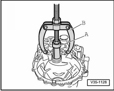
V35-1128

→ Fig.1     Pulling out small taper roller bearing outer race

A - Internal extractor 37 ... 46 mm, e.g. Kukko 21/6

B - Counter support, e.g. Kukko 22/2

 
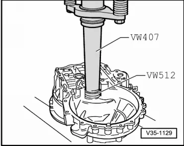
V35-1129

→ Fig.2     Pressing in small taper roller bearing outer race

 
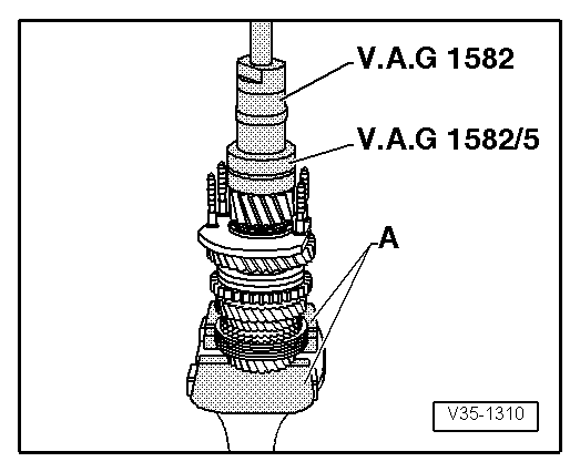
V35-1310

→ Fig.3     Pulling off small taper roller bearing inner race

A - Vice clamps/vice

  • ‒ Fit gripping device and tension behind bearing rollers, then turn bearing and retension gripping device.
 
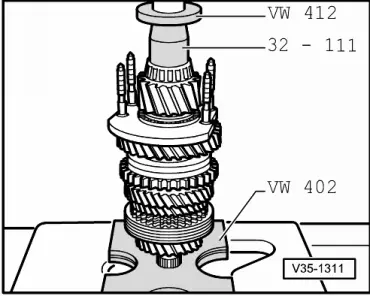
V35-1311

→ Fig.4     Pressing on small taper roller bearing inner race

 
V35-1222

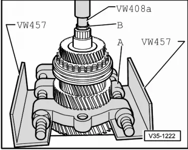
→ Fig.5     Pressing off 3rd and 4th gear synchro-hub/locking collar, 2nd, 3rd and 4th gear wheels with gearbox housing needle roller bearing sleeve

A - Separating device 22 ... 115 mm, e.g. Kukko 17/2

B - Hexagon bolt 17 mm AF - M10 x 20

Note:

Support separating appliance so that the 1st and 2nd gear locking collar is not pulled off at the same time.

 
V35-1221

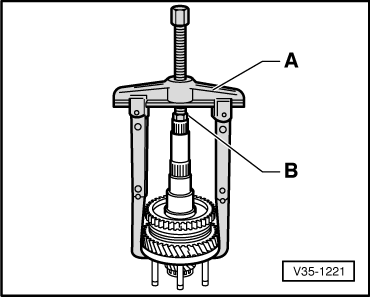
→ Fig.6     Pulling off locking collar with synchro-hub via bearing support

A - Two-arm puller, e.g. Kukko 20/10 with
     250 mm reach hooks

B - Hexagon bolt 17 mm AF - M10 x 20

Note:

Remove circlip before pulling off individual components.

 
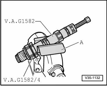
V35-1132

→ Fig.7     Pulling off large taper roller bearing inner race

A - Vice clamps

  • ‒ Before fitting puller insert a M 10 x 20 hexagon bolt in the output shaft drilling.
 
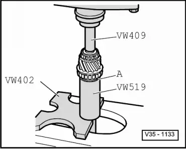
V35-1133

→ Fig.8     Pressing on large taper roller bearing inner race

A - Thrust washer

  • ‒ Fit thrust washer before pressing on the inner race. The shoulder faces the inner race.
 
V35-0975

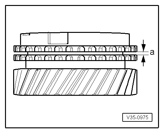
→ Fig.9     Checking synchro-ring for wear

  • ‒ Press synchro-ring onto the gear wheel cone and measure gap "a" with feeler gauge.

Gap "a"

New dimension

Wear limit

1st gear
3rd gear
4th gear

1.0 ... 1.7 mm
1.0 ... 1.7 mm
1.0 ... 1.7 mm


0.5 mm

 
V35-1318

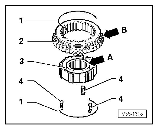
→ Fig.10     Dismantling and assembling 1st and 2nd gear locking collar and synchro-hub

  •      1 -     Spring
  •      2 -     Locking collar
  •      3 -     Synchro-hub
  •      4 -     Locking piece
  • ‒ Slide locking collar over synchro-hub.

The wide shoulder of the synchro-hub (arrow A) and the outer splines of the locking collar (arrow B) face opposite directions after assembly. Recesses for locking pieces on synchro-hub and locking collar must align.

 
V34-0581

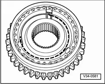
→ Fig.11     Assembling 1st and 2nd gear locking collar/synchro-hub

  • ● Locking collar is pushed over synchro-hub.
  • ‒ Insert locking pieces and install springs 120° off-set. The angled end of the spring must locate in the hollow locking piece.
 
V35-1312

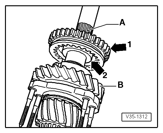
→ Fig.12     Installation position 1st and 2nd gear locking collar/synchro-hub

The locking collar splines (arrow 1) point to splines for 3rd/4th gear synchro-hub -A-.

The wide shoulder of the synchro-hub (arrow 2) then faces to 1st gear -B-.

 
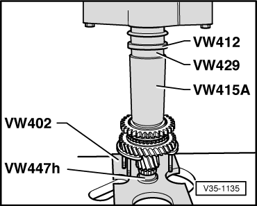
V35-1135

→ Fig.13     Pressing on 1st and 2nd gear locking collar/synchro-hub

Note:

Before pressing on, place 1st gear synchro-ring on 1st gear wheel.

 
V35-1394

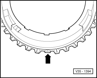
→ Fig.14     Identifying 1st and 2nd gear synchro-rings

  • ◆ 1st gear synchro-ring - 3 x ground down half teeth (arrow)
  • ◆ 2nd gear synchro-ring - 3 x ground down half teeth (arrow) or 2 x ground down half teeth

Only the 2nd gear synchro-ring with 2 x ground down half teeth is available as a spare part.

 
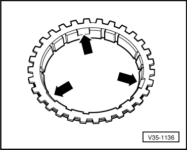
V35-1136

→ Fig.15     Distinguishing 1st and 2nd gear synchro-rings

  • ◆ 1st gear synchro-ring - no recesses
  • ◆ 2nd gear synchro-ring - three recesses (arrows)
 
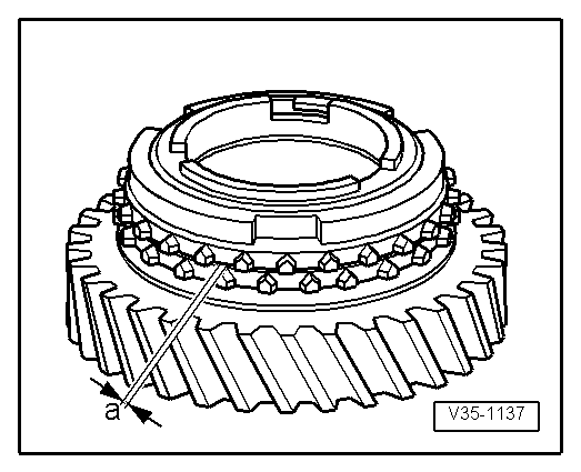
V35-1137

→ Fig.16     Checking 2nd gear synchro-ring for wear

  • ‒ Press synchro-ring, outer-ring and inner-ring onto gear wheel cone and measure gap "a" with feeler gauge.

Gap "a"

New dimension

Wear limit

2nd gear

1.2 ... 1.8 mm

0.5 mm

 
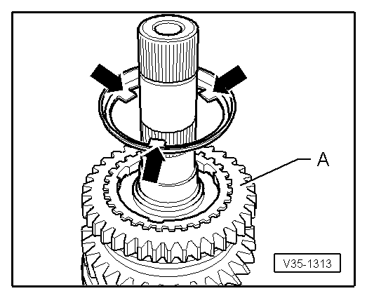
V35-1313

→ Fig.17     Installation position outer-ring

The lugs (arrows) face to 1st gear -A-

 
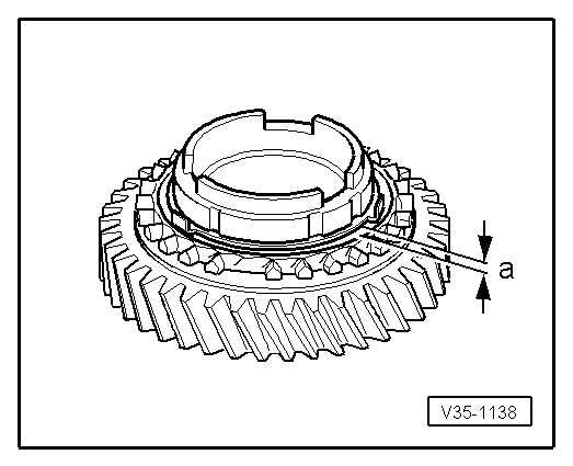
V35-1138

→ Fig.18     Checking inner-ring for wear

  • ‒ Press inner-ring onto 2nd gear wheel cone and measure gap "a" with a feeler gauge.

Gap "a"

New dimension

Wear limit

2nd gear

0.75 ... 1.25 mm

0.3 mm

 
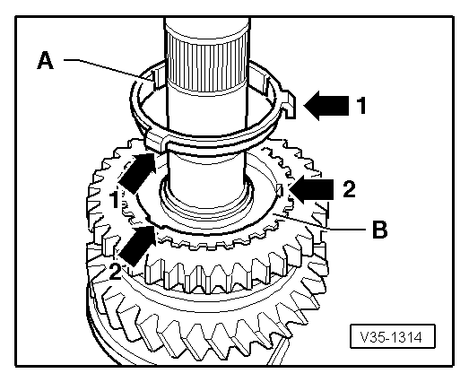
V35-1314

→ Fig.19     Installation position synchro-ring (inner-ring) -A-

The lugs (arrow 1) locate in the recesses (arrow 2) in the synchro-ring -B-.

 
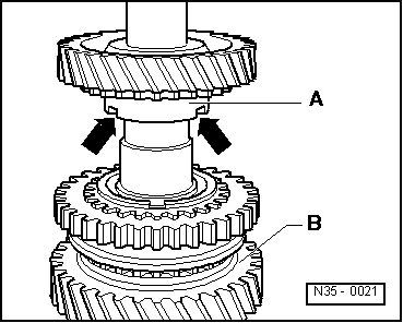
N35-0021

→ Fig.20     Installation position 2nd gear wheel

The higher shoulder -A- faces to 1st gear -B-. The recesses in the shoulder (arrows) locate with the lugs of the outer-ring (arrow => Fig.17 )

 
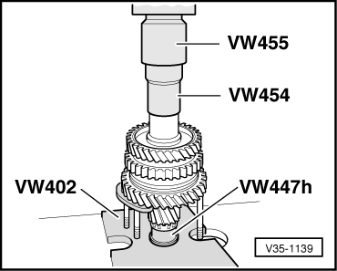
V35-1139

→ Fig.21      Pressing on needle roller bearing sleeve for 3rd gear

 
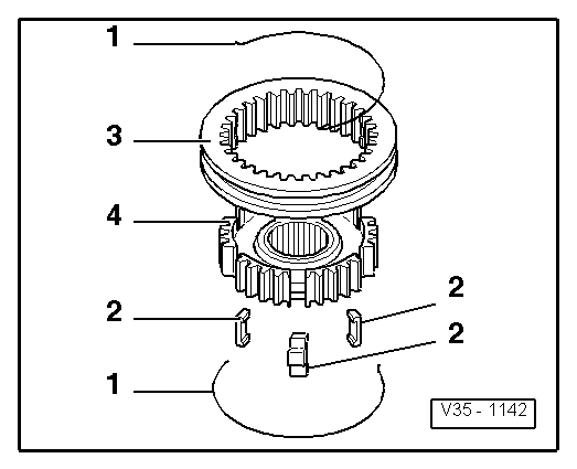
V35-1142

→ Fig.22     Dismantling and assembling 3rd and 4th gear locking collar and synchro-hub

  •      1 -     Spring
  •      2 -     Locking piece
  •      3 -     Locking collar
  •      4 -     Synchro-hub
  • ‒ Slide locking collar over synchro-hub.

The recesses for locking pieces in synchro-hub and locking collar must align.

 
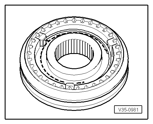
V35-0981

→ Fig.23     Assembling 3rd and 4th gear locking collar/synchro-hub

The locking collar has been pushed over the synchro-hub.

  • ‒ Insert locking pieces and install springs 120° off-set. The angled end of the spring must locate in the hollow locking piece.
 
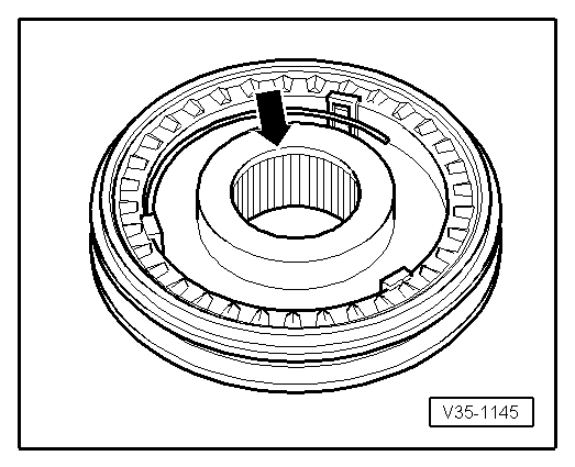
V35-1145

→ Fig.24     Installation position 3rd and 4th gear locking collar/synchro-hub

Chamfer (arrow) faces to 4th gear.

 
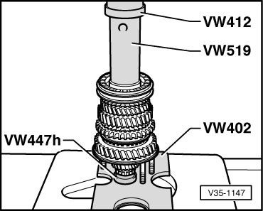
V35-1147

→ Fig.25     Pressing on 3rd and 4th gear synchro-hub with locking collar

 
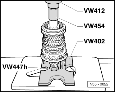
N35-0022

→ Fig.26     Pressing on sleeve for 4th gear needle roller bearing

 
N35-0023

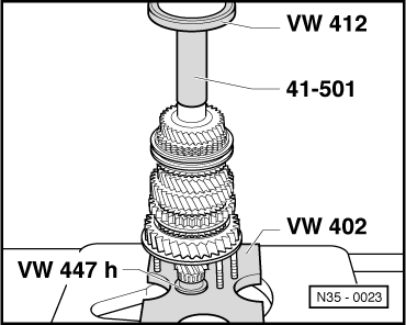
→ Fig.27     Pressing on sleeve for output shaft needle roller bearing

Adjusting output shaft > < Carrying out check measurement