volkswagen Workshop Repair Guides

Volkswagen Workshop Service and Repair Manuals

Servicing propshaft > < Adjusting bevel gear
5 Speed Manual Gearbox 02C four wheel drive
Removing and installing propshaft

A twin pillar lifting platform should be used when working on the propshaft.

Notes:

  • ◆ Before removing, mark the positions of all parts in relation to each other. Reinstall in the same position otherwise imbalance will be excessive, the mountings could be damaged causing rumbling noises.
  • ◆ Keep propshaft straight, only store and transport fully extended.

Removing

 
V40-1061
  • ‒ Detach front exhaust pipe at catalyst, and unhook centre silencer out of both mountings.

=> Repair group 26; Removing and installing parts of exhaust system.

  • ‒ Secure catalyst in lowered position.
  • ‒ → Remove balance weight -A- from assembly carrier, if fitted.
  • ‒ Remove heat shield from above exhaust pipe (below propshaft).
 
V39-1311
  • ‒ → Mark position of front and rear propshaft sections on both constant velocity joints and for bevel box output flange and front flexible coupling with paint (the illustration shows the rear propshaft constant velocity joint).
  • ‒ Mark position of rear flexible coupling balance weights to viscous coupling with paint.
  • ‒ Remove rear axle anti-roll bar.

=> Repair group 42; Servicing rear axle (vehicles with four wheel drive).

Note:

Do not loosen the brake pressure regulator lever clamp on anti-roll bar but after removing anti-roll bar detach spring at lever.

 
V39-1313
  • ‒ Remove securing bolts on front and rear constant velocity joints.
  • ‒ Push front and rear constant velocity joints back until the front and rear propshaft can be moved easily.
  • ‒ Tie front and rear propshafts up.
  • ‒ → Remove both intermediate mountings securing bolts (arrows) and take centre propshaft out.
 
V39-1312
  • ‒ → Unbolt front propshaft from flexible coupling/heat shield (the arrow points to only one of three securing bolts) and carefully pull off centring pin.

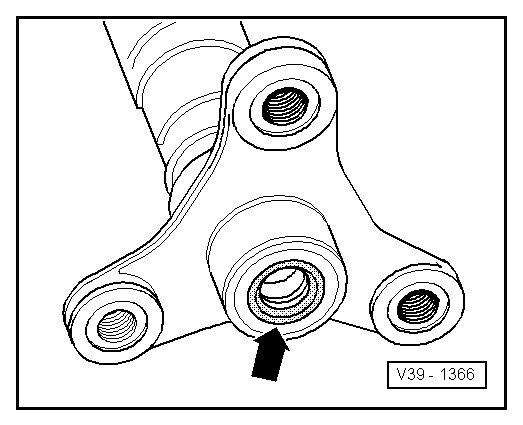
Note:

Pull horizontally off centralizing pin, do not cant propshaft during removal from flexible coupling/heat shield. Centring sleeve seal must not be damaged ( ) otherwise the complete propshaft must be replaced.

 
V39-1454
  • ‒ → Unbolt rear propshaft with flexible coupling -A- and balance weight -B- from the viscous coupling then carefully pull off centralizing pin.

Notes:

  • ◆ Flexible coupling and balance weights cannot be separated from one another.
  • ◆ Pull horizontally off centralizing pin, do not cant propshaft during removal from flexible coupling/heat shield. Centring sleeve seal must not be damaged (=> Page 39-84 ) otherwise the complete propshaft must be replaced.
  • ‒ Push exhaust system down to the right and take out propshaft.

Installing

Installation of the three part propshaft is carried out in the reverse sequence.

 
V39-1366

→ Notes:

  • ◆ Do not damage front/rear propshaft centring sleeve seal (arrow) during installation. Propshaft must not be canted, but push horizontally onto the relevant centring pin. If damaged renew complete propshaft.
  • ◆ Move centre propshaft to and throw in the constant velocity joints so as to obtain the central position before tightening the intermediate mounting bolts to bodywork. Intermediate mountings must be stress free.
  • ◆ Hook anti-roll bar into brake pressure regulator spring and tighten to rear axle body and semi trailing arm to torque setting.

Tightening torques

Intermediate bearing to body

25 Nm

Front/rear shaft to centre propshaft

40 Nm

Flexible coupling to viscous coupling

60 Nm

Flexible coupling to bevel box

45 Nm

Flexible coupling to propshaft

45 Nm

Servicing propshaft > < Adjusting bevel gear