volkswagen Workshop Repair Guides

Volkswagen Workshop Service and Repair Manuals

Checking modulating piston movement sender and quantity adjuster > < Checking Diesel direct injection system current supply
Diesel direct injection and glow plug system
Servicing Diesel direct injection system
Checking fuel temperature sender

Special tools, testers, measuring instruments and auxiliary items required

  • ◆ Fault reader V.A.G 1551 or vehicle system tester V.A.G 1552 with cable V.A.G 1551/3
  • ◆ Test box V.A.G 1598/18
  • ◆ Hand multimeter V.A.G 1526 or multimeter V.A.G 1715
  • ◆ Adapter set V.A.G 1594
  • ◆ Current flow diagram

Test sequence

  • ‒ Connect fault reader V.A.G 1551 and select engine electronics control unit (address word 01); selection is carried out with engine idling.
 
→ Indicated on display:
Rapid data transfer     HELP
Select function XX
  • ‒ Input 08 for "Read measured value block" function and confirm with Q.
 
→ Indicated on display:
Read measured value block     HELP
Input display group number XXX
  • ‒ Press keys 0, 0 and 7 for "Display group number 7" and confirm entry with Q key.
 
→ Indicated on display:
Read measured value block 7     ⇒
15.4 5C          15.9 5C     16.7 5C
  • ‒ Observe display in display zone 1.
  • ‒ In cases of fault, the substitute fuel temperature of -5.6 °C is displayed.
  • ‒ If no realistic value is displayed in display zone 1 or the substitute temperature of -5.6 °C is displayed. Check intake manifold temperature sender and wiring connections to sender as follows:

Electrically checking fuel temperature sender (G81).

  • ‒ Switch off ignition.
  • ‒ Disconnect connector for sender =>Fitting locations overview, Page 23-4 .
 
N23-0007
  • ‒ → Carry out resistance measurement between connector contacts 4 + 7 using hand multimeter V.A.G 1526.
 
N24-0157
  • ‒ → Specifications =>Illustration

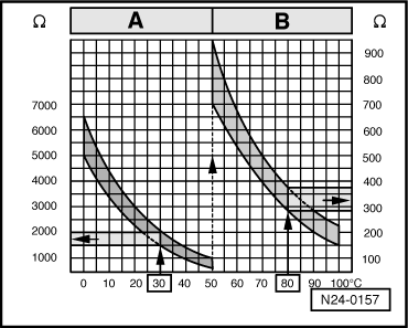
Scale A shows resistance values for temperature range 0...50 °C and scale B the values for temperature range 50...100 °C.

Examples:

  • ◆ 30 °C corresponds to a resistance from 1500...2000 ω
  • ◆ 80 °C corresponds to a resistance from 275...375 ω

If the specification is not attained:

  • ‒ Replace fuel temperature sender (G81)
    => Page 23-33

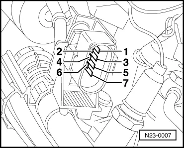
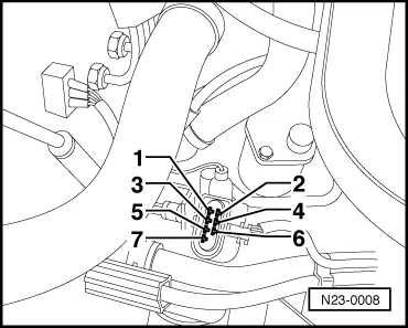
Checking wiring connections to fuel temperature sender (G81)

  • ‒ Switch off ignition.
  • ‒ Disconnect connector for sender =>Fitting locations overview, Page 23-4 .
  • ‒ Connect test box .

The following wiring connections are to be checked for open circuits and/or short to positive or negative.

 
N23-0008
  • ‒ → Wiring from connector contact 7 to test box socket 63.
  • ‒ Wiring from connector contact 4 to test box socket 33.
  • ‒ Rectify any open/short circuit as necessary.
  • ‒ If neither an open or short circuit exists, renew Diesel direct injection system control unit.

Checking modulating piston movement sender and quantity adjuster > < Checking Diesel direct injection system current supply