volkswagen Workshop Repair Guides

Volkswagen Workshop Service and Repair Manuals

Checking needle lift sender > < Checking fuel temperature sender
Diesel direct injection and glow plug system
Servicing Diesel direct injection system
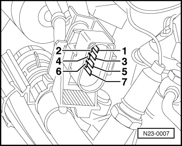
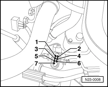
Checking modulating piston movement sender and quantity adjuster

The quantity adjuster is an electro-magnetic swivelling positioner which is controlled by the control unit via a directed duty cycle (on-off ratio). The eccentric shaft on the quantity adjuster moves the modulating piston on the high pressure piston and thereby regulates the quantity of fuel injected.

The modulating piston movement sender informs the control unit of the position of quantity adjuster -N146 and therefore stipulates the amount injected.

Special tools, testers, measuring instruments and auxiliary items required

  • ◆ Fault reader V.A.G 1551 or vehicle system tester V.A.G 1552 with cable V.A.G 1551/3
  • ◆ Test box V.A.G 1598/18
  • ◆ Hand multimeter V.A.G 1526 or multimeter V.A.G 1715
  • ◆ Adapter set V.A.G 1594
  • ◆ Current flow diagram

Test sequence

  • ‒ Connect fault reader V.A.G 1551 and select engine electronics control unit (address word 01); selection is carried out with engine idling.
 
→ Indicated on display:
Rapid data transfer     HELP
Select function XX
  • ‒ Input 08 for "Read measured value block" function and confirm with Q.
 
→ Indicated on display:
Read measured value block     HELP
Input display group number XXX
  • ‒ Press keys 0, 0 and 1 for "Display group number 1" and confirm entry with Q key.
 
→ Indicated on display:
Read measured value block 1     ⇒
840 rpm     6.5 mg/H     1.480 V     87.3 5C
  • ‒ Check display in display zone 4 (coolant temperature).
 
→ Specification: At least 85 °C
Read measured value block 1     "
     840 rpm     6.5 mg/H     1.480 V     87.3 5C

Continue with check when coolant temperature is attained.

  • ‒ Check display in display zone 3 (voltage supplied from modulating piston movement).
 
→ Specification:
     Engine code 1Z, AHU 1.250...1.750 V
     Engine code AFN 1.450...1.900 V
Read measured value block 1     ⇒
840 rpm     6.5 mg/H     1.480 V     87.3 5C
  • ‒ If specification is not attained. Check modulating piston movement sender and quantity adjuster as described in following:
 
N23-0007

Electrically checking modulating piston movement sender (G149).

  • ‒ Switch off ignition.
  • ‒ Disconnect connector for sender =>Fitting locations overview, Page 23-4 .
  • ‒ → Carry out resistance measurement between contacts 1 + 2 and 2 + 3 using hand multimeter V.A.G 1526.
         Specification: 5 ... 7 ω

If the specification is not attained:

  • ‒ Replace injection pump.

Checking wiring connection to modulating piston movement sender (G149)

  • ‒ Switch off ignition.
  • ‒ Disconnect connector for sender =>Fitting locations overview, Page 23-4 .
  • ‒ Connect test box .

The following wiring connections are to be checked for open circuits and/or short to positive or negative.

 
N23-0008
  • ‒ → Wiring from connector contact 1 to test box socket 29.
  • ‒ Wiring from connector contact 2 to test box socket 7.
  • ‒ Wiring from connector contact 3 to test box socket 52.
  • ‒ If neither an open or short circuit exists, renew Diesel direct injection system control unit.
 
N23-0007

Electrically checking quantity adjuster (N146)

  • ‒ Switch off ignition.
  • ‒ Disconnect connector for quantity adjuster =>Fitting locations overview, Page 23-4 .
  • ‒ → Carry out resistance measurement between contacts 5 + 6 using hand multimeter V.A.G 1526.
         Specification: 0.5 ... 2.5 ω

If the specification is not attained:

  • ‒ Replace injection pump.

Checking wiring connections to quantity adjuster (N146)

  • ‒ Switch off ignition.
  • ‒ Disconnect connections for quantity adjuster (N146) =>Fitting locations overview, Page 23-4 .
  • ‒ Connect test box .

The following wiring connections are to be checked for open circuits and/or short to positive or negative.

 
N23-0008
  • ‒ → Wiring from connector contact 5 to test box sockets 23, 45 and 68.
  • ‒ Wiring from connector contact 6 to test box sockets 4, 5, 30 and 49.
  • ‒ Rectify any open/short circuit as necessary.
  • ‒ If neither an open or short circuit exists, renew Diesel direct injection system control unit.

Checking needle lift sender > < Checking fuel temperature sender